Brush cutter

a brush cutter and tooth technology, applied in the direction of peelers, cocoa, kitchen equipment, etc., can solve the problems of frequent maintenance frequent damage to the assembly and/or the collar, and early failure of the teeth, so as to increase the efficiency of the brush cutter, increase the life of the tooth, and facilitate tooth installation and replacement.

Active Publication Date: 2013-10-08
ALAMO GROUP
View PDF16 Cites 26 Cited by
  • Summary
  • Abstract
  • Description
  • Claims
  • Application Information

AI Technical Summary

Benefits of technology

[0008]It is the purpose of the present invention to provide an improved cutting tooth for a brush cutter which tooth, when mounted on the brush cutter, will: increase the life of the tooth, allow for easier tooth installation and replacement, increase the efficiency of the brush cutter, and reduce maintenance. It is a further purpose of the present invention to provide a cutting assembly for a brush cutter, incorporating the improved cutting tooth in a mounting block, which assembly will easily yet securely mount the tooth while locating it in an efficient cutting position. It is a further purpose of the present invention to provide a brush cutter incorporating the tooth and the cutting assembly in a manner to allow efficient cutting with the tooth able to take larger ‘bites’ of the brush than normal making the machine more efficient. It is another purpose to have the brush cutter position the teeth for easy replacement and mounting and for easy sharpening. It is a further purpose to have the brush cutter position the teeth in a manner to have the cutting section of the tooth approaching a tangential position relative to the peripheral edge of the collars so that the cutting edge tends to retain its radial distance from the center of rotation of the edge even after numerous sharpenings which shorten the tooth.
[0009]In accordance with the present invention, a cutting tooth is provided having a blade-like cutting section integral with a mounting section on the tooth. The cutting section is spaced from the mounting section by a connector section and extends forwardly of the mounting and connecting sections to terminate in a cutting edge. The cutting tooth is mounted on a mounting block to form a cutting assembly for a brush cutter. The mounting block is a parallelpiped adapted for mounting between adjacent protective collars on a brush cutter drum. The block is mounted at the peripheral edge of the collars above the surface of the drum. The cutting tooth and mounting block are designed to have the cutting tooth quickly and easily, yet extremely securely, mounted in the mounting block. The manner of mounting of the tooth on the block makes replacement quick and simple. The cutting tooth is mounted to have the cutting section above the mounting block with the cutting section extending forwardly of the mounting block. With the assembly mounted on the protective collars, the cutting section of the tooth, located above the collars, allows the tooth to engage and cut more of the brush on each rotation making it more efficient. The tooth is mounted to have the cutting section generally tangentially located with respect to the cutting circle described by the cutting edge of the tooth during operation. Cutting and impact forces are thus transmitted mainly in compression against the cutting section. The tangential and extended position of the cutting section on and from the mounting block increases the ability of the cutter to grasp more brush thus increasing efficiency. It also positions the cutting edge in a more exposed position making sharpening easier. The tangential position also ensures that the cutting edge remains in generally the same radial location after sharpening thus minimizing any reduction in efficiency due to shortening of the blade. The tooth is preferably spaced radially outwardly from the periphery of the collars at least about a distance equal to half the thickness of the tooth. The cutting section of the tooth is further sized and positioned to have the cutting edge at least about a third of the length of the cutting section in front of the mounting block.

Problems solved by technology

Since the mounting blocks and the teeth thereon are exposed on the surface of the drum, the brush cutters require frequent maintenance both in replacing damaged elements of the cutting assemblies, and in keeping the cutting teeth sharp.
However the assemblies extend laterally from the collars and the tooth assemblies often make initial contact with the unsupported, lateral, sections of the assemblies during cutting resulting in frequent damage to the assemblies and / or collars.
If the teeth extend too far upwardly above the collars and mounting blocks, the teeth are subject to large bending forces resulting in early failure of the teeth.
If the teeth do not extend too far above the collars and mounting block, the teeth have a small bite when cutting brush and thus are not very efficient.

Method used


Image

  • Brush cutter
  • Brush cutter
  • Brush cutter

Examples


Embodiment Construction

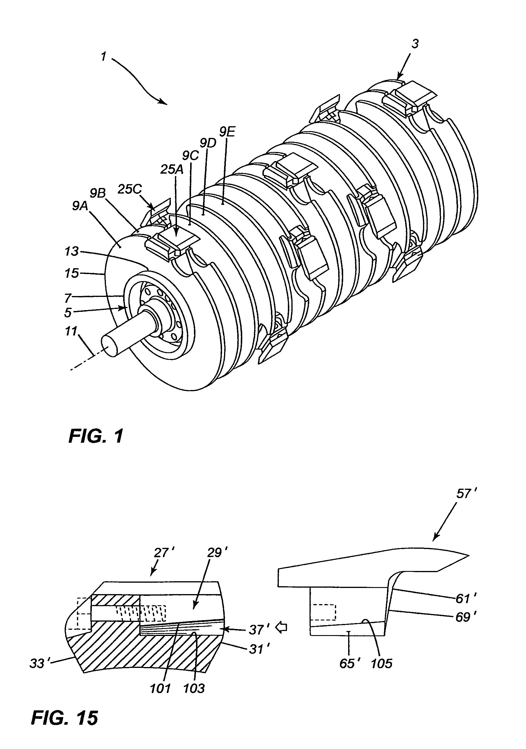
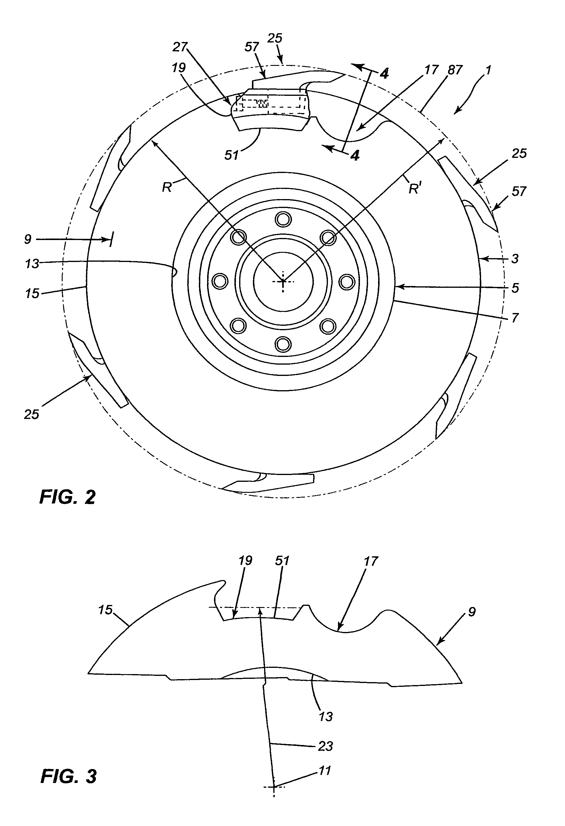
[0027]The brush cutter 1 of the present invention, as shown in FIGS. 1 to 3, has a rotatable drum 3. The drum 3 includes a central, tubular member 5 having a cylindrical surface 7. Annular collars 9 are mounted on the tubular member 5, the collars of equal size and equally spaced-apart and transverse to the longitudinal, central axis 11 of the tubular member 5. Each collar 9 has an inner circular periphery 13, sized to just receive the member 5 there through, and an outer periphery 15. The outer periphery 15 is also preferably circular but it could also have helical sections. Each collar 9 is welded onto the surface 7 of the tubular member 5. The drum 3 is mounted at its ends in any well known manner in a frame (not shown) that carries the drum and the drum is rotatable in the frame about its axis 11 by suitable drive means, (not shown).

[0028]Each collar 9 has at least one first cutout 17 extending radially inwardly from the outer periphery 15 of the collar. The cutout 17 has a gene...


PUM


Abstract

A cutting tooth having a blade-like cutting section and a mounting section extending down from the bottom of the cutting section. The mounting section is narrower and shorter than the cutting section, and generally centered with respect to the cutting section. The mounting section has laterally extending flanges spaced from the cutting section. At least a quarter of the cutting section extends past the front of the mounting section and terminating in a cutting edge.The cutting tooth is adapted to be mounted in a mounting block to form a cutting assembly. The mounting block has a slot extending into the block from the front face, the slot open in the top surface of the block. The mounting section of the tooth slides into the slot in the block to locate the cutting section on the top of the block with the cutting section projecting forwardly of the block. The flanges on the tooth hold the tooth in place in the block against centrifugal forces. The cutting assembly is adapted to be mounted between two collars on a brush cutting drum with the cutting tooth above the periphery of the collars.

Description

CROSS-REFERENCE TO RELATED APPLICATIONS[0001]This application claims priority on provisional U.S. application No. 61 / 344,453 filed Jul. 26, 2010, the entire content of which is incorporated by reference herein.BACKGROUND OF THE INVENTION[0002]1. Technical Field[0003]This invention relates to a cutting tooth for a brush cutter. The invention further relates to a cutting assembly for a brush cutter. The invention also relates to a brush cutter incorporating the cutting assembly.[0004]2. Background Art[0005]Brush cutters employing a cylindrical, rotatable, drum with cutting assemblies mounted on the drum, the drum mounted on the front of a vehicle or on a boom on a vehicle, are known. The cutting assemblies each generally comprise a mounting block fixed on the drum with a cutting tooth detachably mounted on the block. Since the mounting blocks and the teeth thereon are exposed on the surface of the drum, the brush cutters require frequent maintenance both in replacing damaged elements ...

Claims


Application Information

Patent Timeline
Patent Type & Authority Patents(United States)
IPC IPC(8): B02C18/18
CPCA01G23/00B02C18/146B02C18/184B02C18/18B02C18/14
Inventor DENIS, LAURENTDENIS, GILLES
Owner ALAMO GROUP
Why Eureka
Try Eureka