Normally-open solenoid valve including plunger formed with pressure receiving portion

a solenoid valve and plunger technology, which is applied in the direction of valve details, valve arrangements, braking systems, etc., can solve the problems of increasing the size of the valve, and increasing the flow rate of the operating fluid between the valve seat and the plunger, so as to increase increase the seat diameter, and reduce the diameter of the forward end.

Active Publication Date: 2013-10-08
HITACHI ASTEMO LTD
View PDF18 Cites 10 Cited by
  • Summary
  • Abstract
  • Description
  • Claims
  • Application Information

AI Technical Summary

Benefits of technology

[0003]In order to design a solenoid valve capable of treating a greater flow rate, it is generally desirable to increase a seat diameter and to decrease the diameter of a forward end of a plunger. However, the flow of the operating fluid between the valve seat and plunger becomes fast with increase of the flow rate, and tends to develop a negative pressure which acts to pull the plunger, and induce vibrations of the plunger. The addition of a damper chamber as in the above-mentioned patent document is disadvantageous in that the size of the valve is increased. Therefore, it is an object of the present invention to provide a solenoid valve for suppressing vibrations and preventing a size increase of the valve.

Problems solved by technology

However, the flow of the operating fluid between the valve seat and plunger becomes fast with increase of the flow rate, and tends to develop a negative pressure which acts to pull the plunger, and induce vibrations of the plunger.
The addition of a damper chamber as in the above-mentioned patent document is disadvantageous in that the size of the valve is increased.

Method used


Image

  • Normally-open solenoid valve including plunger formed with pressure receiving portion
  • Normally-open solenoid valve including plunger formed with pressure receiving portion
  • Normally-open solenoid valve including plunger formed with pressure receiving portion

Examples


first embodiment

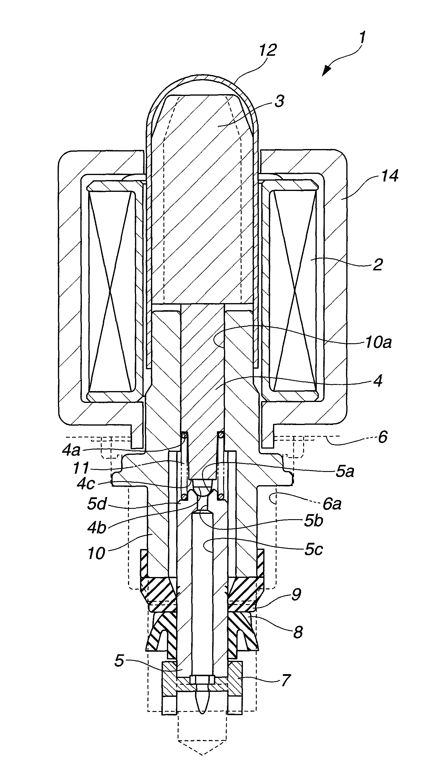
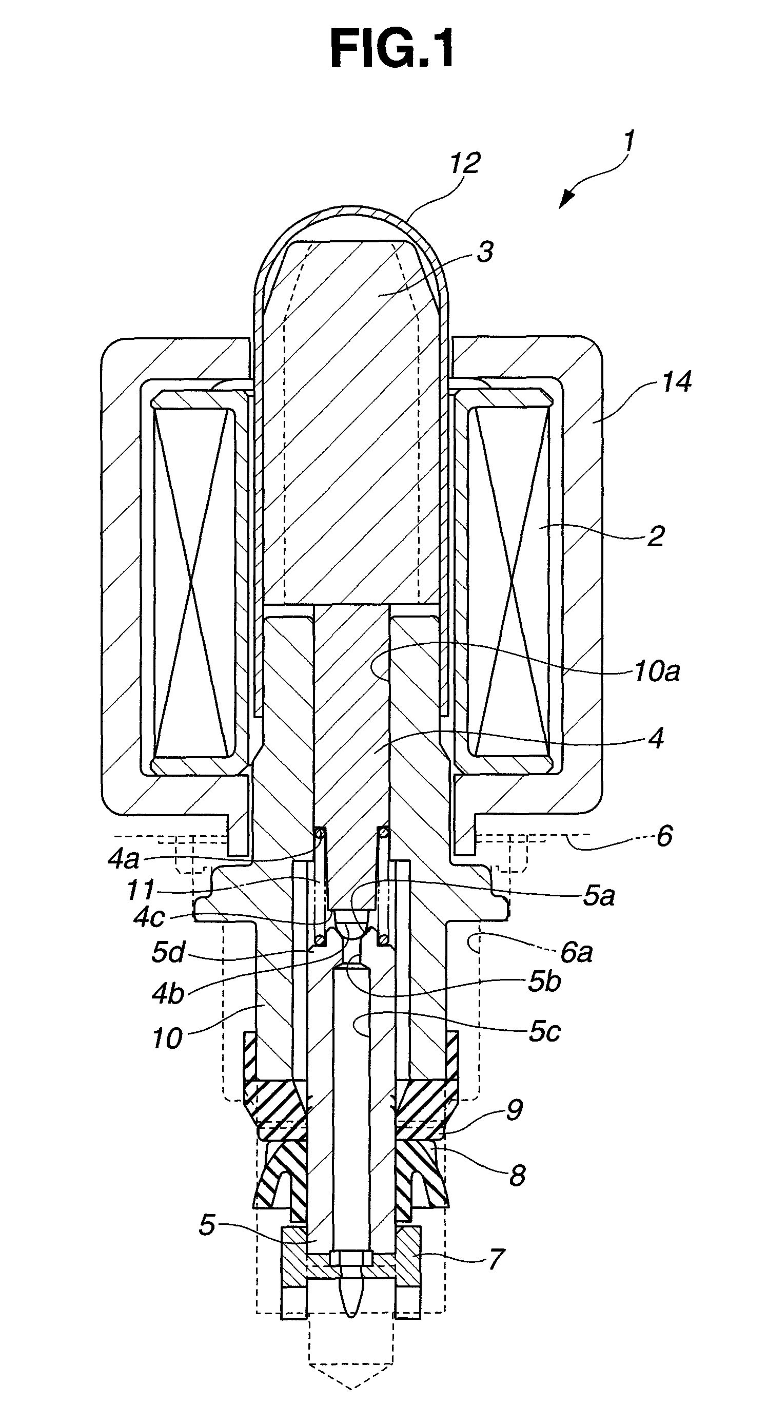
[0014][Structure of Solenoid valve] A solenoid valve or electromagnetic valve 1 according to a first embodiment of the present invention is a normally-open valve to be used in a brake system of a vehicle. FIG. 1 shows the solenoid valve 1 in section. Solenoid valve 1 includes a solenoid coil 2 to produce an electromagnetic force when energized, an armature 3 made of magnetic material and arranged to actuated by the electromagnetic force, a plunger 4 to move as a unit with armature 3, a valve seat 5 having an orifice hole 5b opened and closed by plunger 4, and a valve body 10 housing the plunger 4.

[0015]The valve seat 5 includes a seat portion 5a, a spring receiving (or retaining) portion 5d (serving as a base from which the seat portion 5a projects axially) and a fluid passage 5c. The seat portion 5a is formed at a first end of valve seat 5 extending axially or longitudinally from the first end to a second end. Seat portion 5a is a funnel-shaped portion having a recess tapering to t...


PUM


Abstract

A solenoid valve includes a solenoid coil, a yoke of magnetic material, an armature of magnetic material to move in an axial direction of the solenoid coil when the solenoid coil is energized, a plunger to be moved with the armature, a valve seat member including a seat portion formed with a valve hole to be closed and opened by a forward end portion of the plunger, and a coil spring which is disposed between a spring receiving portion of the plunger and the valve seat member, around the plunger. The plunger includes a pressure receiving portion (such as a flat portion) which extends in a radial direction of the plunger at a position between the forward end portion and the spring receiving portion of the plunger, and which faces to the seat portion.

Description

BACKGROUND OF THE INVENTION[0001]The present invention relates to normally-open type solenoid valve or electromagnetic valve.[0002]A patent document JP2008-121721A shows a normally-open solenoid valve including a damper chamber behind a plunger, and an elastic member disposed between the damper chamber and a valve chamber receiving a valve element, and designed to define a throttle passage. The elastic member functions to increase the cross sectional size of the throttle passage by deformation just after opening of the valve, and thereby to facilitate the flow of an operating fluid toward the damper chamber, to suppress self excited vibrations.SUMMARY OF THE INVENTION[0003]In order to design a solenoid valve capable of treating a greater flow rate, it is generally desirable to increase a seat diameter and to decrease the diameter of a forward end of a plunger. However, the flow of the operating fluid between the valve seat and plunger becomes fast with increase of the flow rate, and...

Claims


Application Information

Patent Timeline
Patent Type & Authority Patents(United States)
IPC IPC(8): F16K31/06
CPCB60T8/363F16K31/0665
Inventor YOSHIDA, KEIGOSAITA, NORIHIRODOI, SATOSHIYOKOTA, TADAHARU
Owner HITACHI ASTEMO LTD
Why Eureka
Try Eureka