Clock movement containing a constant force device

a constant force device and clock movement technology, applied in the direction of clock driving mechanism, frequency stabilisation mechanism, instruments, etc., can solve the problems of amplitude of mechanical oscillator oscillation, difficult assembly, small-sized movement complex, etc., and achieve precise and simple manner

Inactive Publication Date: 2013-10-08
LA MONTRE HERMES
View PDF9 Cites 6 Cited by
  • Summary
  • Abstract
  • Description
  • Claims
  • Application Information

AI Technical Summary

Benefits of technology

[0013]Consistent with embodiments of the present invention, a clock movement is provided that contains a constant force device of simple construction, which as far as possible limits the disturbances, linked to its working, which could influence the running of the time base of the movement and the load state of the secondary spring of which can be adjusted in a precise and simple manner.
[0015]According to an embodiment, the watchmaker may act upon the movement in order to regulate the load state of the spiral spring relatively easily, even when the movement is running. In fact, unlike known mechanisms, there is no need to remove any element whatever of the movement in order to regulate the load state of the spiral spring.

Problems solved by technology

These small-sized movements are complex and hence tricky to assemble.
In particular, the amplitude of the oscillations of the mechanical oscillator, critical for the running accuracy of the movement, is difficult to adjust, particularly as it depends on the load state of the secondary spring.
When the operation has to be realized later, within the framework of the after-sales service, it has again the same complexity.
Nevertheless, the adjustment of the load state of the secondary spring by means of this mechanism remains perilous, in particular when the movement is running.
It is nevertheless notable that this constant force device, though of complex construction, does not propose means by which the load state of the secondary spring can be easily adjusted.

Method used


Image

  • Clock movement containing a constant force device
  • Clock movement containing a constant force device
  • Clock movement containing a constant force device

Examples


embodiment (

Embodiment(s) of the Invention

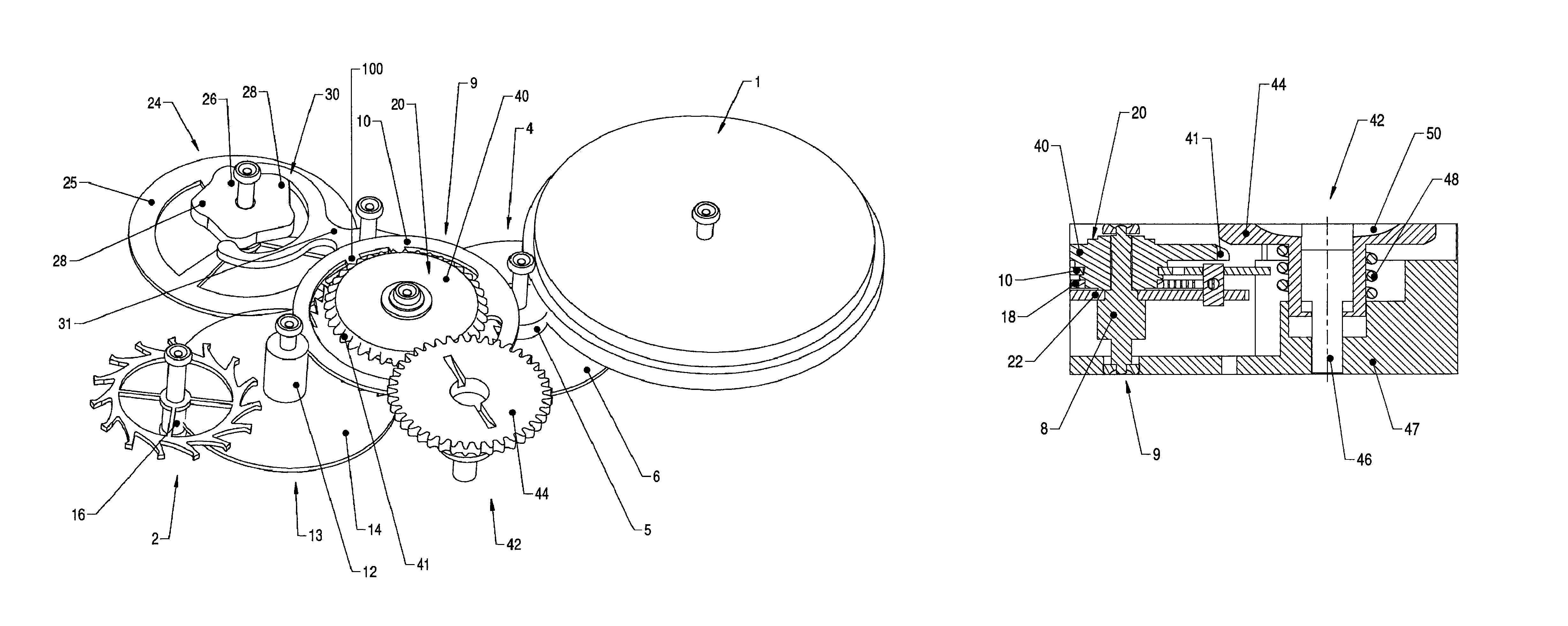
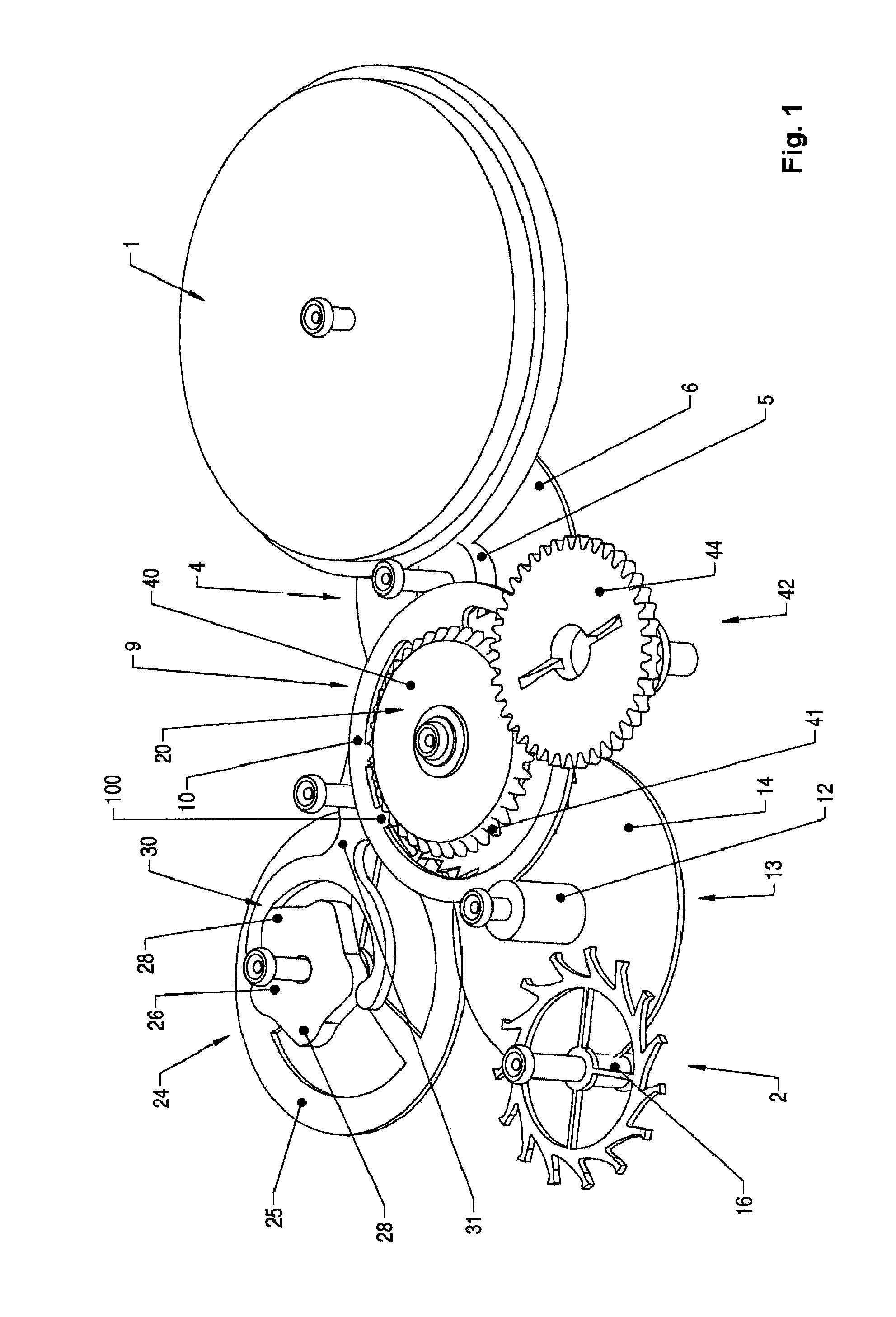
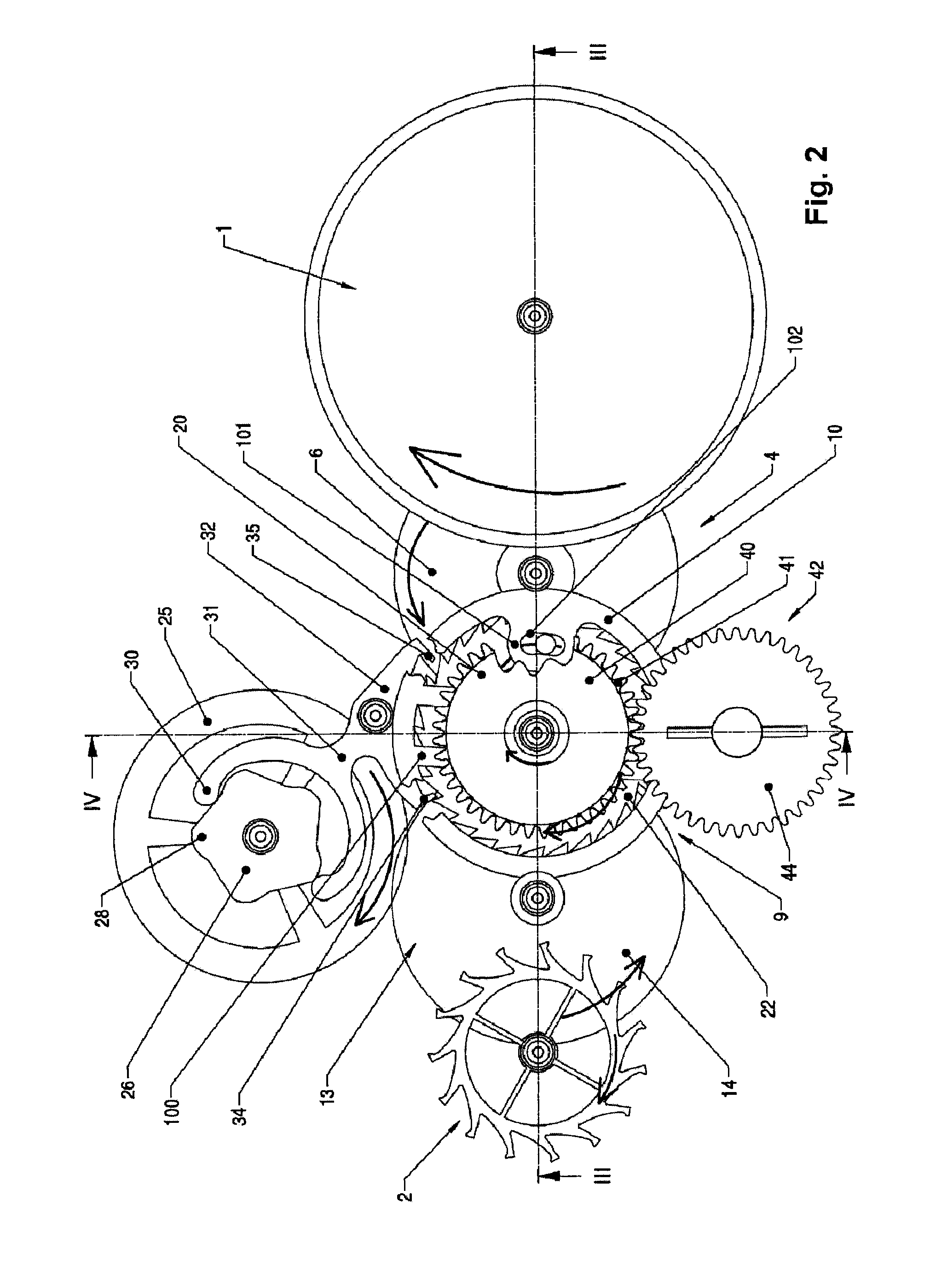
[0032]The structure and general working of an embodiment of the present invention will be explained in association with FIGS. 1, 2 and 3, representing the movement respectively in perspective, in plan view and in section. Only those elements which contribute to an understanding of the invention are illustrated, for greater clarity. Certain elements of FIG. 2 are shown in partially cut-away representation in order to make visible other elements which are superimposed on them.

[0033]According to an embodiment, a clock movement containing constituent members has been illustrated in FIGS. 1 to 3, in particular a barrel 1 accommodating a mainspring (non-visible) and designed to supply energy to the mechanical oscillations of a time base of which only the escape wheel 2 has been represented. The energy of the mainspring is transmitted via a work train comprising a centre mobile 4, the pinion 5 of which is in mesh with the toothing of the barrel drum and the wh...


PUM


Abstract

A clock movement is provided that contains a constant force device. In accordance with one implementation, the clock movement includes a spiral spring, and a train, having a first kinematic chain arranged to connect a main energy source to a first end of the spiral spring and a second kinematic chain for connecting a time base to a second end of the spiral spring. One of the first and second kinematic chains may contain an adjustment mobile comprising first and second members connected to each other by a friction such that a rotation of one member drives the other member during routine working of the clock movement. One of these members may include an adjustment member having at least one bearing surface arranged such that it is possible to act upon the latter so as to rotate the adjustment member without rotating the other member by dint of friction, in order to adjust the load state of the spiral spring.

Description

[0001]This application is a national stage filing under 35 U.S.C. §371 of International Application No. PCT / EP2009 / 059902, filed on Jul. 30, 2009, which claims priority to European Application No. 08105371.2, filed on Sep. 18, 2008, the disclosures of which are expressly incorporated herein by reference to their entireties.BACKGROUND[0002]1. Technical Field[0003]The present invention relates to a clock movement containing a constant force device, comprising a spiral spring, and a train, having a first kinematic chain arranged to connect a main energy source to a first end of the spiral spring and a second kinematic chain for connecting a time base to a second end of the spiral spring.[0004]2. Prior Art[0005]Numerous clock movements of the abovementioned type, containing constant force devices, have long been described.[0006]By way of example, U.S. Pat. No. 1,237,216, describes a clock movement containing a primary mainspring, of sizeable power reserve, and a secondary mainspring, of...

Claims


Application Information

Patent Timeline
Patent Type & Authority Patents(United States)
IPC IPC(8): G04B18/00
CPCG04B1/225
Inventor WIEDERRECHT, JEAN-MARC
Owner LA MONTRE HERMES
Why Eureka
Try Eureka