Stereo display apparatus and lens array thereof
a technology of which is applied in the field of stereo display apparatus and lens array, can solve the problems of viewing the inability to achieve vivid stereo scenes
- Summary
- Abstract
- Description
- Claims
- Application Information
AI Technical Summary
Benefits of technology
Problems solved by technology
Method used
Image
Examples
first embodiment
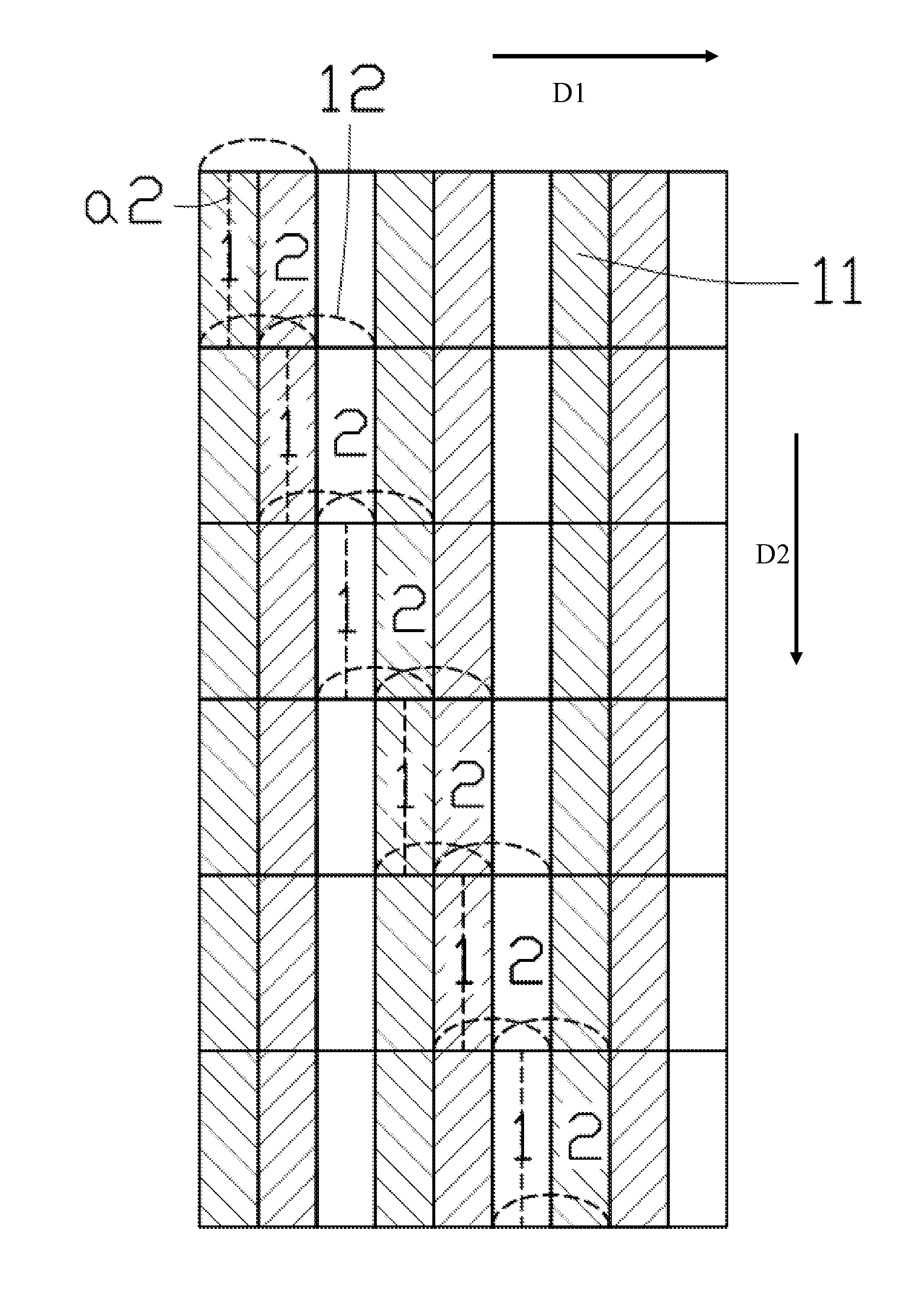
[0020]Referring to FIG. 4, a stereo display apparatus according to the present disclosure is a 2-view stereo display apparatus, and includes a pixel array and a lens array.
[0021]The pixel array includes a plurality of pixel units 11 arrayed in parallel rows and parallel columns. A direction along which the pixel units 11 are arrayed in rows is hereinafter defined as a first direction D1, and a direction along which the pixel units 11 are arrayed in columns is hereinafter defined as a second direction D2. In the illustrated embodiment, the pixel units 11 may be RGB (red, green and blue) pixel units of a liquid crystal display (LCD) apparatus or pixel units for independent address of other kind of display apparatuses. The pixel units 11 display first images (labeled as 1 in FIG. 4) and second images (labeled as 2 in FIG. 4) along the first direction D1, alternately. Every two adjacent first images or second images have a stagger arrangement, and a staggered step therebetween equals to...
second embodiment
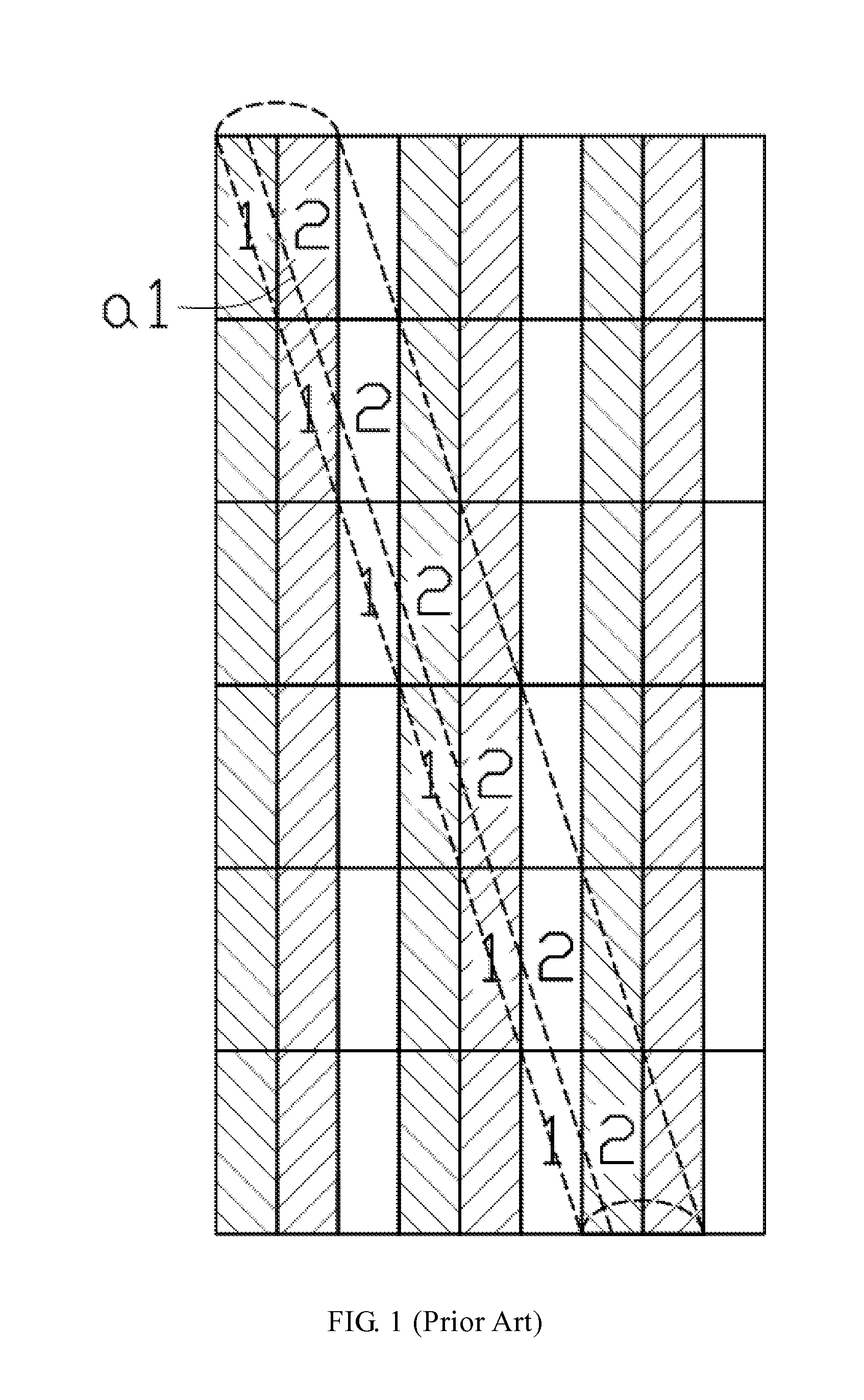
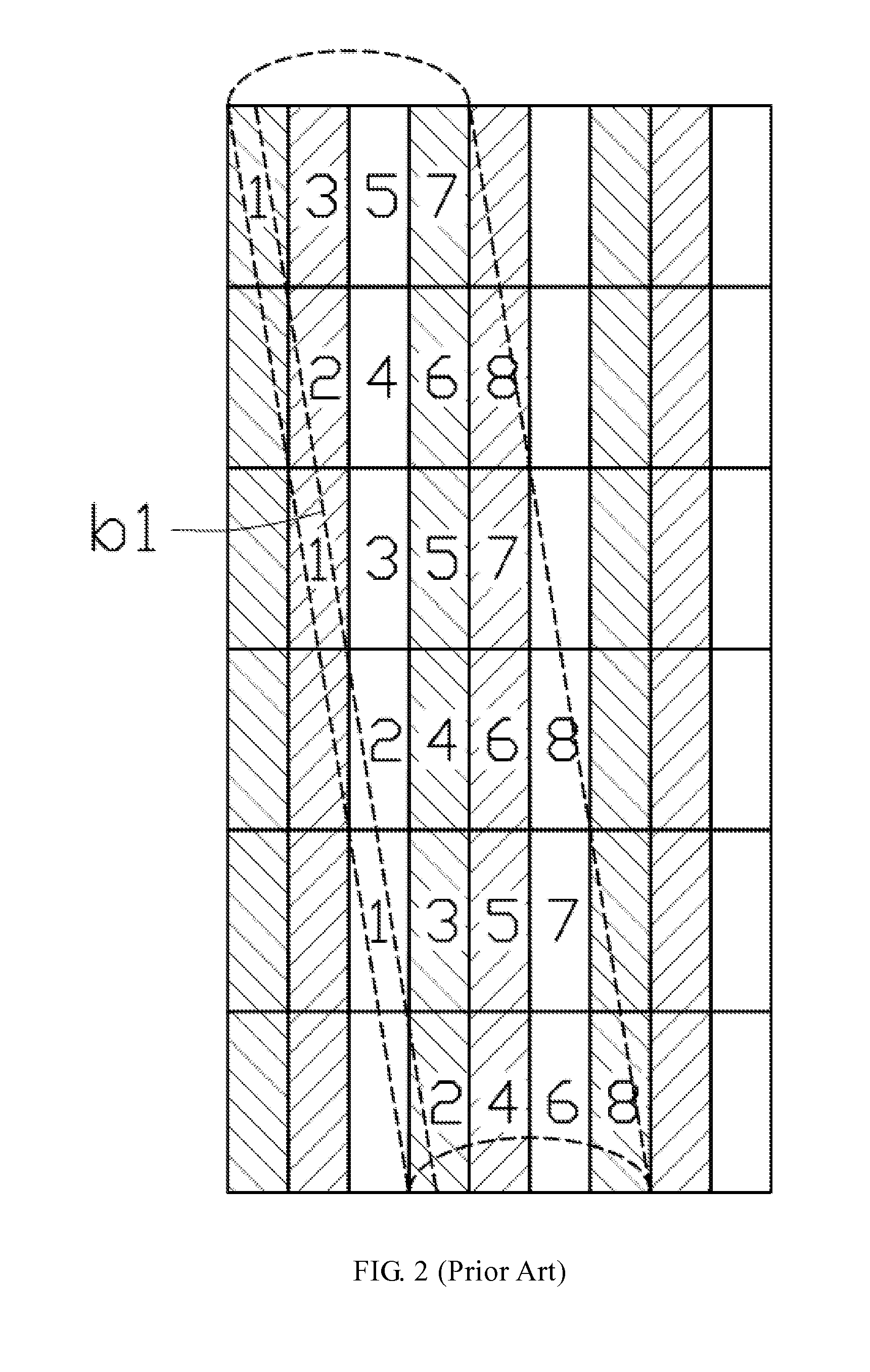
[0027]Because the adjacent lens units 12 are arranged in terraced steps, images of one same kind in different rows are corresponding to the portions of the lens units 12 with same optical features, and may be further guided toward a same visual angle. Referring to a dashed line b2 of FIG. 5, only the images 3 are guided to the dashed line b2. Compared with the dashed line b1 of FIG. 2, the stereo display apparatus of the second embodiment may solve the problem of interference or crosstalk between left eye images and right eye images, and vivid 3D scenes may be viewed.
[0028]Arrangement of the lens units 12 of FIG. 4 and FIG. 5 are schematic, and should not be limitations to the present disclosure.
[0029]In alternative embodiments, each lens unit 12 may cover n pixel units 11 along the first direction D1 and r pixel units 11 along the second direction D2. Every two adjacent lens units 12 arrayed along the second direction D2 have a stagger arrangement along the first direction D1, and ...
third embodiment
[0036]A principle of the stereo display apparatus of the third embodiment will be described below.
[0037]Referring to FIG. 6, the common electrode 65 receives a reference voltage. The working electrodes 61, 62 receive operating voltages, respectively, which means different operating voltages may be applied to the connection electrodes 63, 64. Thus, voltage differences are generated between the common electrode 65 and the working electrodes 61, 62, respectively. For example, the voltage difference between the common electrode 65 and the working electrode 61 is greater than that between the common electrode 65 and the working electrode 62. The voltage difference therefore generates an electric field in the liquid crystal layer 66, and the electric field intensity is centrosymmetric, with a center where the working electrode 61 is located and an edge where the working electrode 62 is located. Liquid crystal molecules of the liquid crystal layer 66 are arrayed along a direction of the el...
PUM
 Abstract
Description
Claims
Application Information
 - R&D
- Intellectual Property
- Life Sciences
- Materials
- Tech Scout
- Unparalleled Data Quality
- Higher Quality Content
- 60% Fewer Hallucinations
Browse by: Latest US Patents, China's latest patents, Technical Efficacy Thesaurus, Application Domain, Technology Topic, Popular Technical Reports.
© 2025 PatSnap. All rights reserved.Legal|Privacy policy|Modern Slavery Act Transparency Statement|Sitemap|About US| Contact US: help@patsnap.com


