Check patentability & draft patents in minutes with Patsnap Eureka AI!

System and method for pipeline padding

a pipeline padding and system technology, applied in the field of earth and material handling equipment, can solve the problems of limited relative movement of excavated material, less excavated material being filtered, and disadvantages of this system, and achieve the effect of increasing the efficiency of the filtering techniqu

Active Publication Date: 2013-10-15
CRONK JR THOMAS J +1
View PDF17 Cites 0 Cited by
  • Summary
  • Abstract
  • Description
  • Claims
  • Application Information

AI Technical Summary

Benefits of technology

The solution increases the efficiency of filtering by up to 300% compared to prior art, enabling more effective deposition of fines onto the pipeline while allowing coarse material to be returned to the windrow.

Problems solved by technology

There is, however, a disadvantage to this system.
Due to the close proximity, as the rotating scoop members begin to lift the excavated material, the material is retained between the scoop members and screen surface or rods until the respective scoop member has been rotated upwardly by the drum to the upper portion of the path of rotation, thereby resulting in limited relative movement of the excavated material with respect to the rods or screen surface resulting in less excavated material being filtered during a rotation.

Method used


Image

  • System and method for pipeline padding
  • System and method for pipeline padding
  • System and method for pipeline padding

Examples


Embodiment Construction

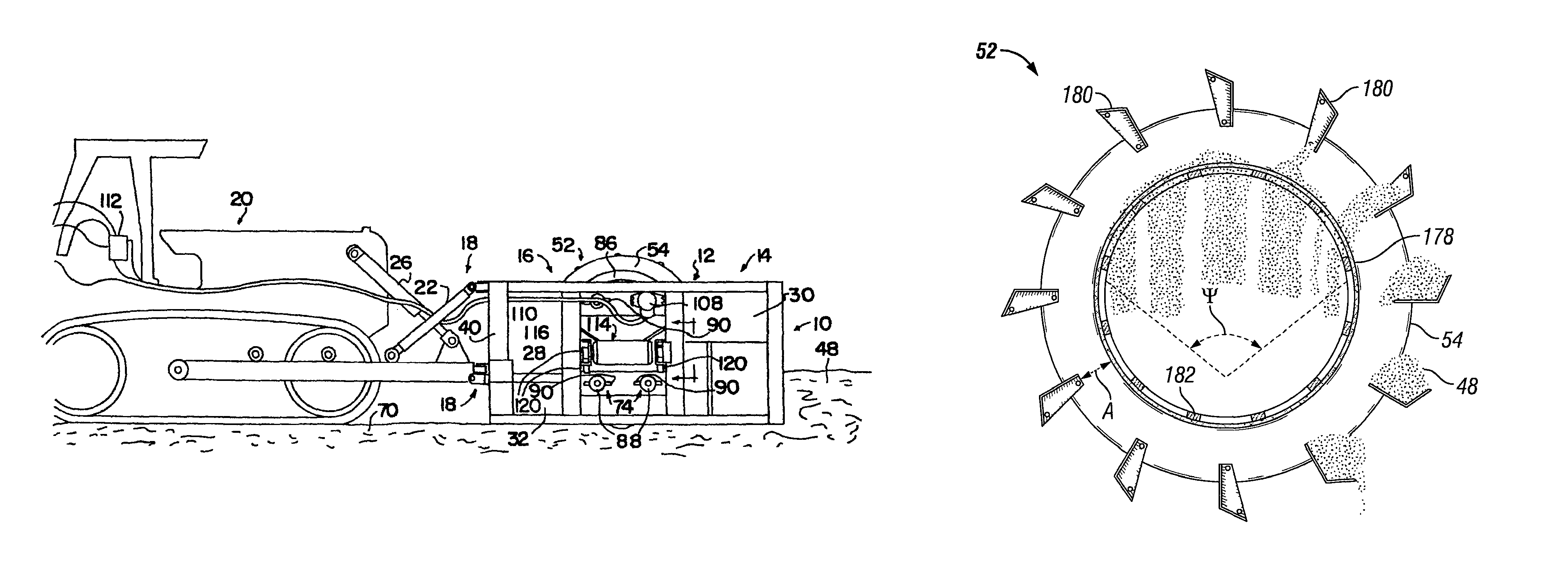
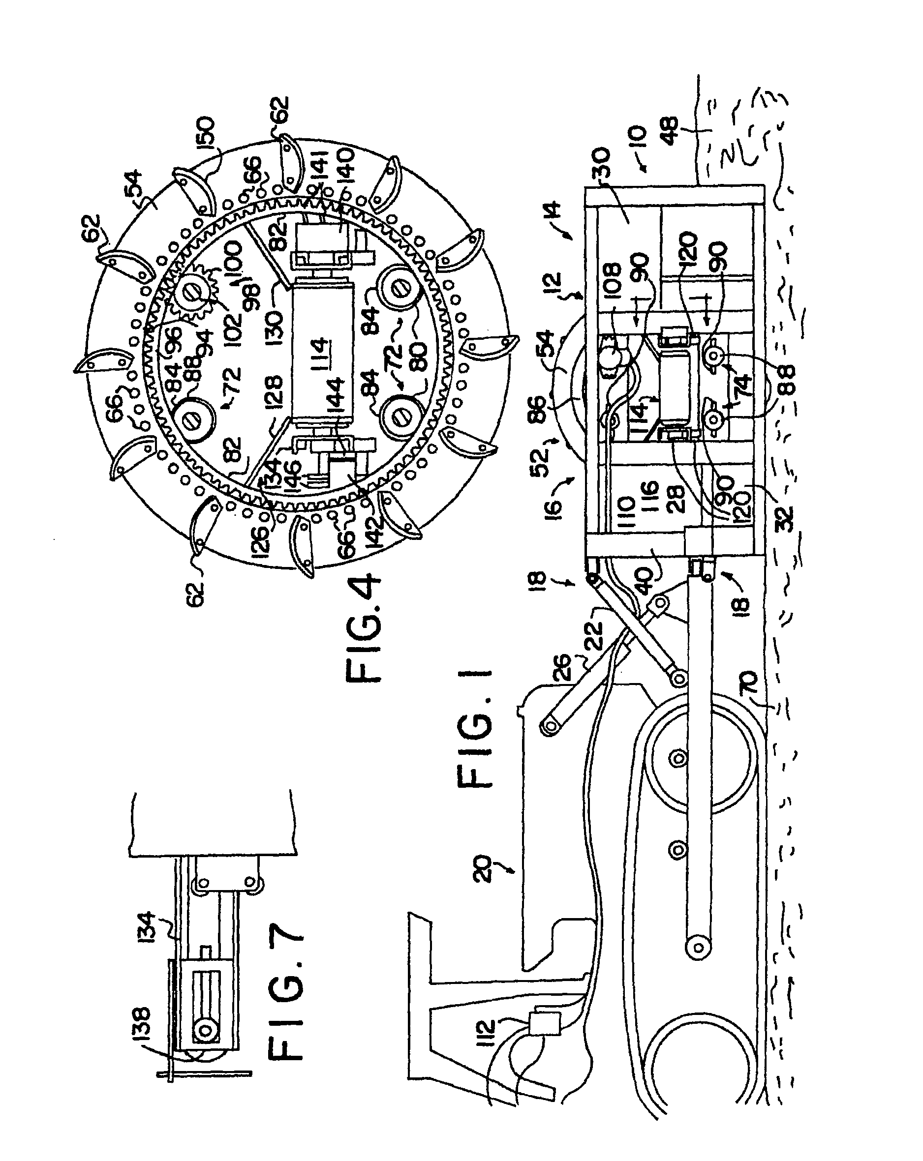
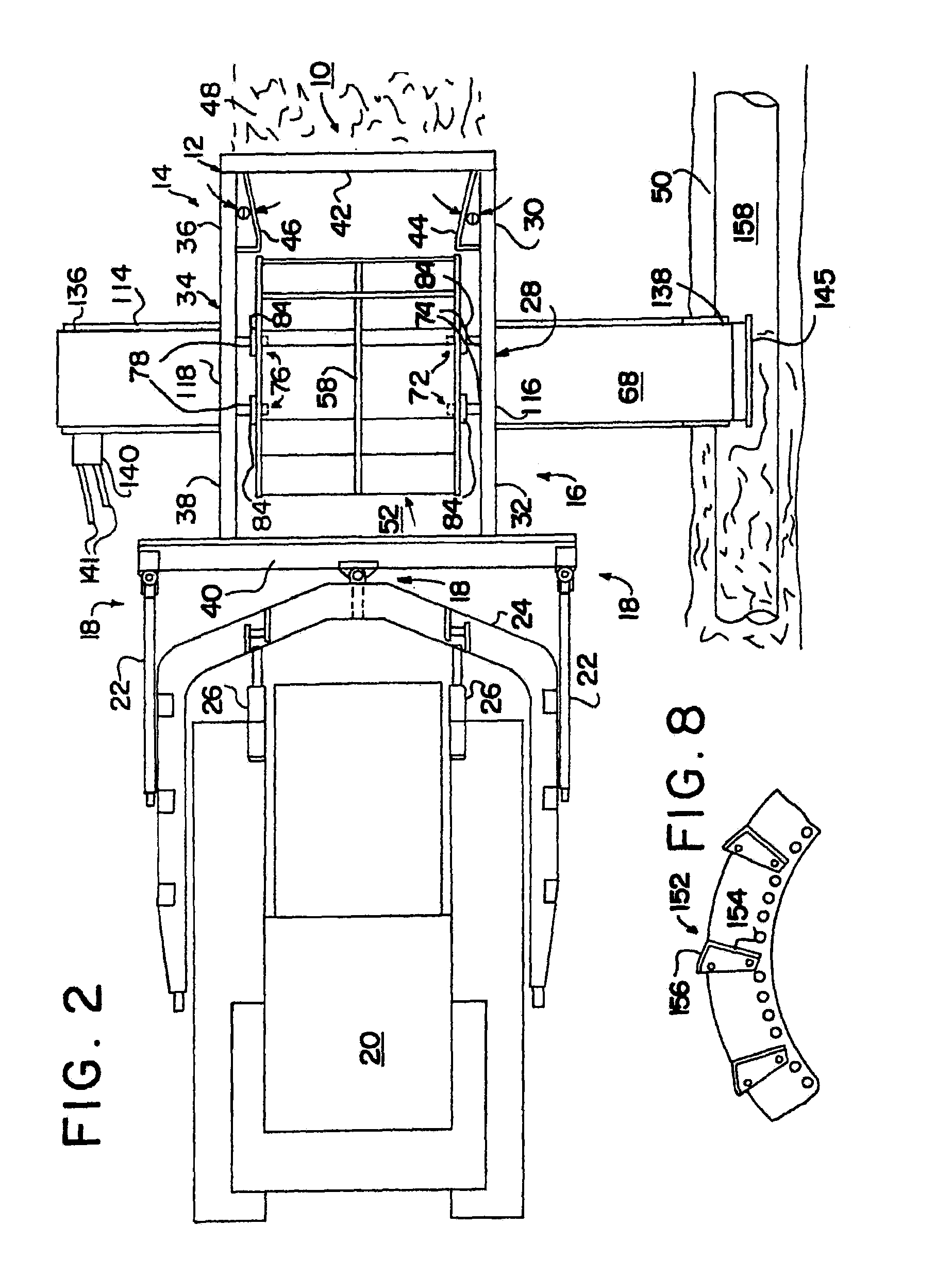
[0023]Illustrative embodiments and methodologies of the invention are described below as they might be employed in a pipeline padder or method of use thereof. In the interest of clarity, not all features of an actual implementation are described in this specification. It will of course be appreciated that in the development of any such actual embodiment, numerous implementation-specific decisions must be made to achieve the developers' specific goals, such as compliance with system-related and business-related constraints, which will vary from one implementation to another. Moreover, it will be appreciated that such a development effort might be complex and time-consuming, but would nevertheless be a routine undertaking for those of ordinary skill in the art having the benefit of this disclosure. Further aspects and advantages of the various embodiments and methodologies of the invention will become apparent from consideration of the following description and drawings.

[0024]Referrin...


PUM


Abstract

An apparatus for padding a pipeline lying in a ditch separates fine particles from coarse particles in the material excavated from the ditch and windrowed along the side of the ditch. The apparatus includes a frame having an open ended hollow separating drum having a plurality of scoop members adapted to lift and drop excavated material through a screen located beneath the scoop members. The scoop members are spaced above the screen a distance such that the efficiency of the separating drum is increased.

Description

FIELD OF THE INVENTION[0001]The present invention relates generally to earth and material handling equipment and, more particularly, to an improved method and apparatus for separating a windrow of excavated material alongside a ditch into fine particles of dirt (“fines”) and coarse particles that include clods and large rocks, and depositing the fines into the ditch and the coarse material back onto the windrow of excavated material.BACKGROUND OF THE INVENTION[0002]Cross country pipelines are usually coated with a corrosion-resistant substance. To protect the coating from damage when the ditch is back filled with excavated material, which may contain large rocks, the pipeline is first covered with fine particles of dirt to serve as a protective padding around the pipeline.[0003]U.S. Pat. No. 5,084,991, issued to Cronk Jr. on Feb. 4, 1992, discloses a system for pipeline padding and is hereby incorporated by reference in its entirety. The disclosed system provides for padding of a pi...

Claims


Application Information

Patent Timeline
Patent Type & Authority Patents(United States)
IPC IPC(8): E02F5/22
CPCE02F5/12E02F5/226
Inventor CRONK, JR., THOMAS J.CRONK, BILLY W.
Owner CRONK JR THOMAS J
Features
  • R&D
  • Intellectual Property
  • Life Sciences
  • Materials
  • Tech Scout
  • Unparalleled Data Quality
  • Higher Quality Content
  • 60% Fewer Hallucinations
Learn More