Drain cover for generally open flat drainage areas with debris blockage and open drainage portions

a flat drainage area and drainage cover technology, applied in the field of drain covers, can solve the problems of flooding situations, damage that is often measured in the thousands, and the type of drains is only possible against, and achieve the effect of great strength

Inactive Publication Date: 2013-10-15
SUTHERLAND MARK
View PDF37 Cites 53 Cited by
  • Summary
  • Abstract
  • Description
  • Claims
  • Application Information

AI Technical Summary

Benefits of technology

[0011]In one embodiment, the top of the device is generally open having an “X” shaped structural element spanning across diameters of the plate; thereby providing the largest apertures possible while also providing structural support for the drain cover and any large objects place or traversing thereon. The “X” shape of the element is such so as to provide great strength with as little material as possible to thereby have the largest openings for water. The structural element allows the device to be light weight, open to significant water flow and allows the device to be traversed by something as weighty as a person or a vehicle on a driveway. It will be understood that the “X” shape also prevents larger object, such as balls or children's toys or the like, from being brought into the drain or from jamming or blocking the drain.

Problems solved by technology

For example, on road surfaces, the presence of water can result in dangerous hydroplaning and other flooding conditions causing safety hazards.
However, these types of drains are only possible against curbs as the skirt portion is typically quite elevated (so as to be effective only during periods of high water) and would prove a high obstacle on a flat surface.
Each of these shows variable sized openings but are of a type that can only be used in the side of the curb on a roadway, due to their large size and shape and which could not be adopted for flat surface use.
However, in areas of generally open flat areas, such as patios and driveways that are in proximity to a house or other structure, the use of drains that have small holes or slots so as to permit drainage of water alone, often cause flooding situations when the small holes or slots become blocked by debris.
This flooding has deleterious effects on the nearby house or structure and / or other property, causing damages that are often measured in the thousands of dollars.
For example, U.S. Patent Application Publication No. 2005 / 0247612, Glassheim, Silt and Debris Filtering System for Storm Drains, tries to solve the problem by capturing the large debris within a drain, but there is a requirement for the user to occasionally come and clear out the debris trap, and in the interim flooding can occur.
U.S. Pat. No. 6,793,811, Fleischmann, Runoff Drain Filter with Separately Removable Cartridges, shows a more modern approach to run off filters, but suffers the same issues and is also not appropriate to flat surface drainage.
However, the '913 and '948 patents suffer the problem that when debris is brought towards the drain, with the natural flow of water, these drains will likely be clogged allowing the surface to flood.
The height of the devices claimed and shown in these patents makes them unsuitable for flat surfaces where pedestrians will walk or vehicles will traverse, as the devices will prove an impediment to safe travel.
Further, the designs have a similar flaw in that they are raised above the surface such that the use of such drains on flat dry surfaces would prove a hazard to travel; their placement in a swimming pool, particularly in the deep end, causes no such hazard.

Method used


Image

  • Drain cover for generally open flat drainage areas with debris blockage and open drainage portions
  • Drain cover for generally open flat drainage areas with debris blockage and open drainage portions
  • Drain cover for generally open flat drainage areas with debris blockage and open drainage portions

Examples


Embodiment Construction

[0027]While the present invention is susceptible of embodiment in various forms, there is shown in the drawings a number of presently preferred embodiments that are discussed in greater detail hereafter. It should be understood that the present disclosure is to be considered as an exemplification of the present invention, and is not intended to limit the invention to the specific embodiments illustrated. It should be further understood that the title of this section of this application (“Detailed Description of an Illustrative Embodiment”) relates to a requirement of the United States Patent Office, and should not be found to limit the subject matter disclosed herein.

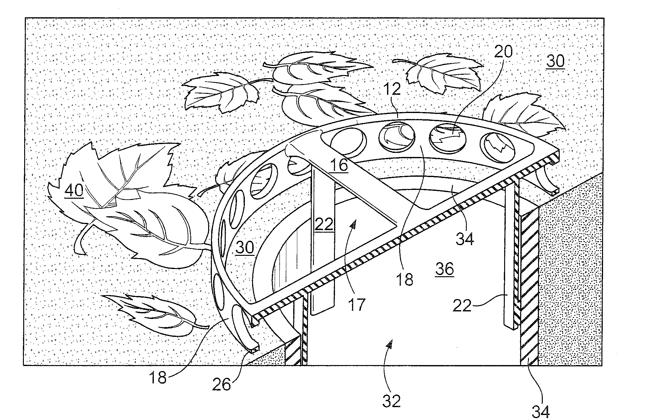
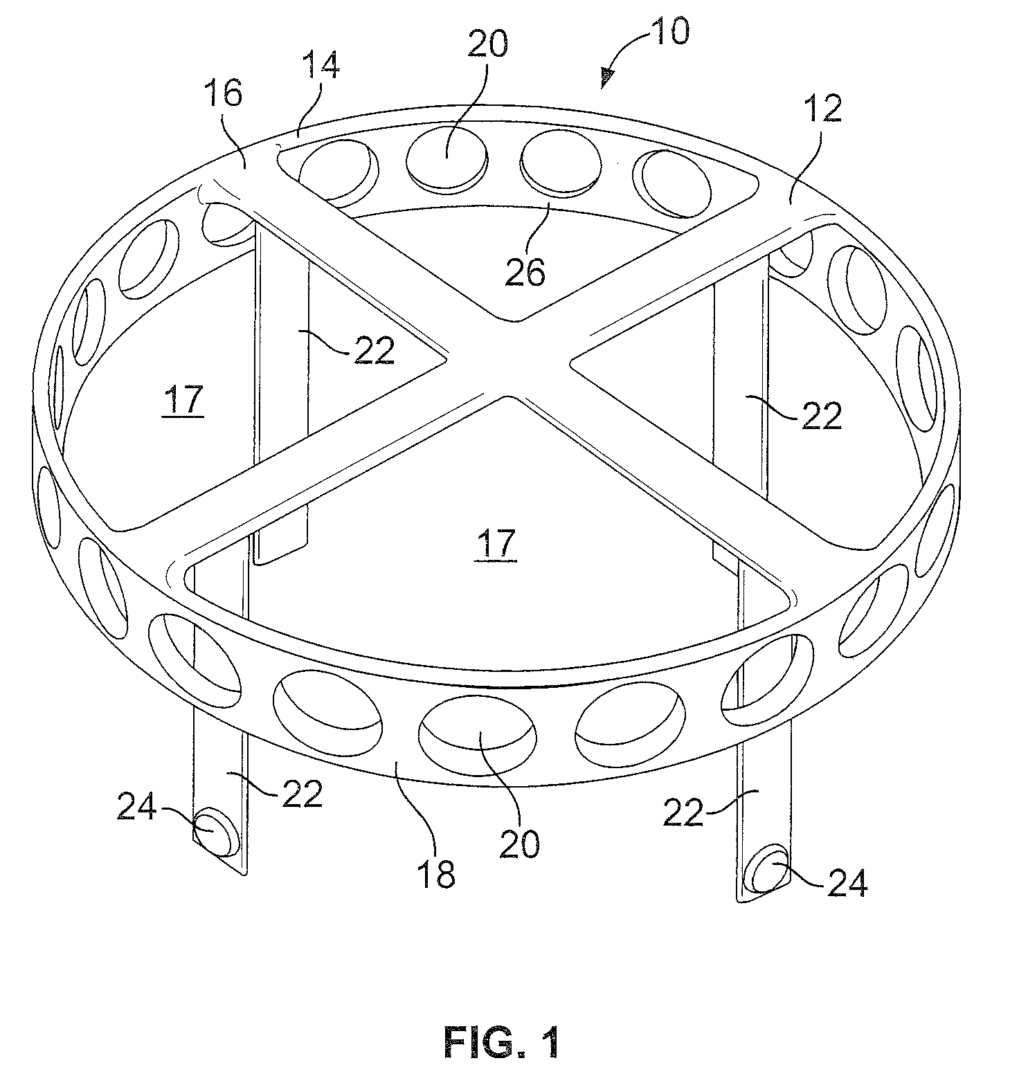
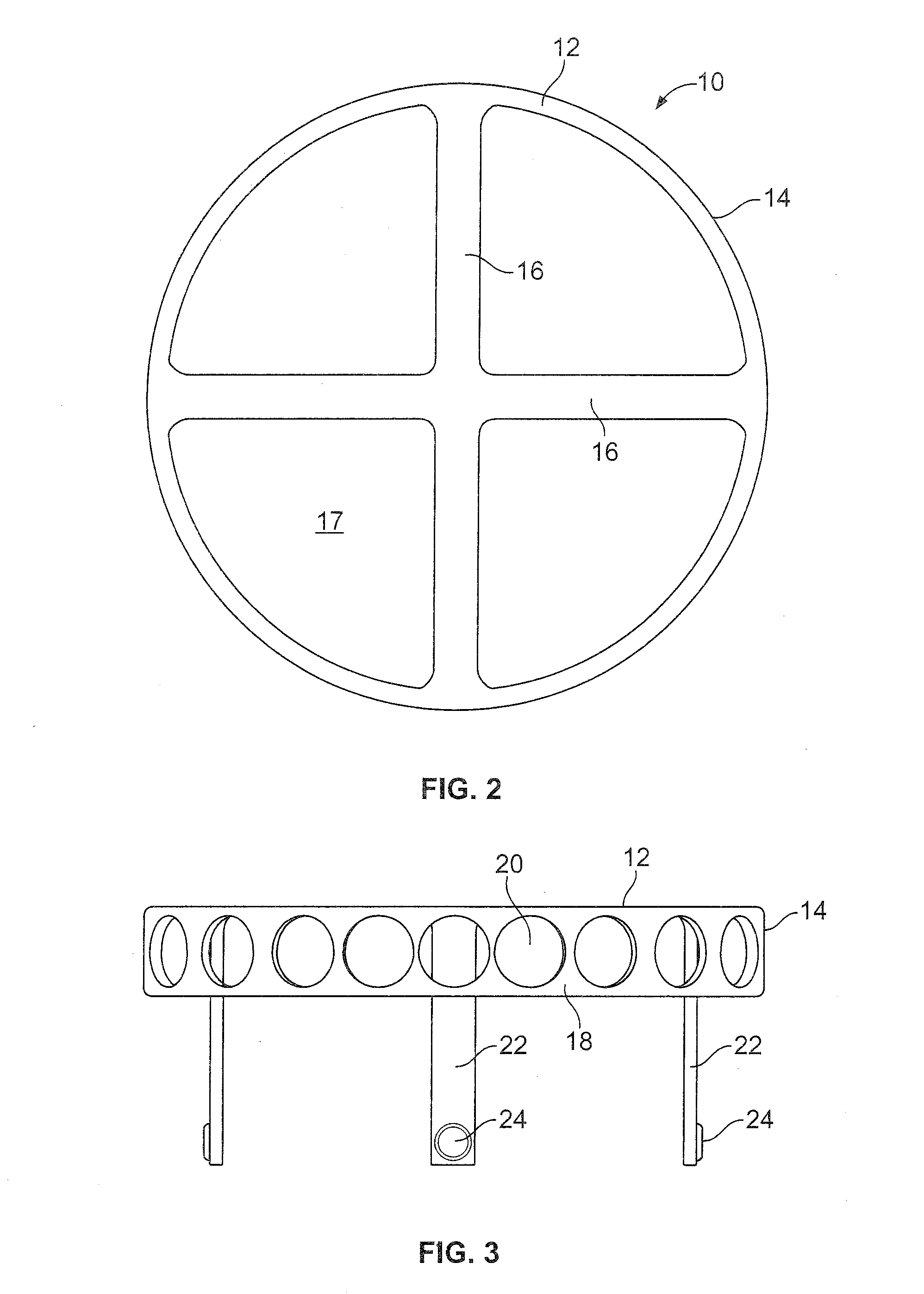
[0028]Referring now to the drawings, it will be seen that FIGS. 1, 2 and 3 show a drain cover 10 of the present invention. It will be seen that drain cover 10 comprises a top surface 12 having a rim 14 and cross member supports 16. It will be understood that the top surface 12 can be configured in various manners, as wi...


PUM


Abstract

A drain cover having a main drainage surface with relatively larger apertures or openings therein, comprising generally 50 percent of the surface, so that larger debris is accepted into a related drain pipe when a depending skirt portion of the drain cover, having smaller perforations, becomes clogged. In this way a two-layer drainage system for a generally flat surface is provided that allows draining of water and small particulates alone when possible, but upon the clogging of the smaller openings the generally flat surface can be protected from flooding by allowing larger particulates to drain into the main drainage surface. The main drainage surface is held above the flat surface by the depending skirt, at a level of ⅜ to 1 inch above the flat surface. When the depending skirt openings are clogged the water and debris will rise until allowed to drain into the larger openings of the main drainage surface.

Description

FIELD OF THE INVENTION[0001]The present invention concerns a drain cover for use on drainage pipes that are within generally open flat surfaces prone to flooding. More particularly the present invention concerns a drain cover having a generally flat surface, open to a drainage pipe and a skirt depending from the flat surface for drainage of water even in the presence of debris that otherwise would block the drain. The skirt and flat surface portions of the drain cover each overlying the surface to be drained in a manner that permits drainage while preventing flooding due to the blockage of drain holes. The device in a preferred embodiment is used outside of a walk-out basement or another entry door that is close to or, below grade and as such is prone to flooding. Further, the device can also be adapted for use within drains in window-wells.BACKGROUND OF THE INVENTION[0002]Presently there are drain covers for use on driveways, patios, walk-out basement doors below grade, interior sp...

Claims


Application Information

Patent Timeline
Patent Type & Authority Patents(United States)
IPC IPC(8): E03F5/14
CPCE03F5/0404E03F5/0409
Inventor SUTHERLAND, MARK
Owner SUTHERLAND MARK
Why Eureka
Try Eureka