
Manufacturing method for a magnetic head supporting suspension

a manufacturing method and magnetic head technology, applied in the direction of manufacturing tools, integrated arm assemblies, instruments, etc., can solve the problems of difficult to obtain stable flying height properties, unbalance of moment attributable to static roll angle, unbalance of moment in rolling direction, etc., to achieve accurate regulation and suppress contamination

Active Publication Date: 2013-10-22
NHK SPRING CO LTD
View PDF5 Cites 1 Cited by
  • Summary
  • Abstract
  • Description
  • Claims
  • Application Information

AI Technical Summary

Benefits of technology

The present invention provides a method for manufacturing a suspension and a suspension assembly that can accurately adjust the position of a load beam and a flexure, while also preventing contamination. This improves the alignment accuracy of the suspension components, allowing for better performance of the suspension.

Problems solved by technology

The unbalance of the moment in the rolling direction is attributable to the static roll angle and dislocation of the dimple.
Thus, unbalance of the moment attributable to the static roll angle occurs.
Actually, however, the accuracy of assembly of the load beam 11 and flexure 12 varies, so that it is difficult to obtain stable flying height properties.
The contamination is harmful to disk drives.
With additional miniaturization of modern suspensions, moreover, the pitch between the reference holes 20 and 21 has been reduced so much that it has become difficult to obtain satisfactory positioning accuracy.
However, even this example is not a solution to the problem of the clearances between the reference holes and jig pins.

Method used


Image

  • Manufacturing method for a magnetic head supporting suspension
  • Manufacturing method for a magnetic head supporting suspension
  • Manufacturing method for a magnetic head supporting suspension

Examples


Embodiment Construction

[0053]One embodiment of the present invention will now be described with reference to FIGS. 1 to 4.

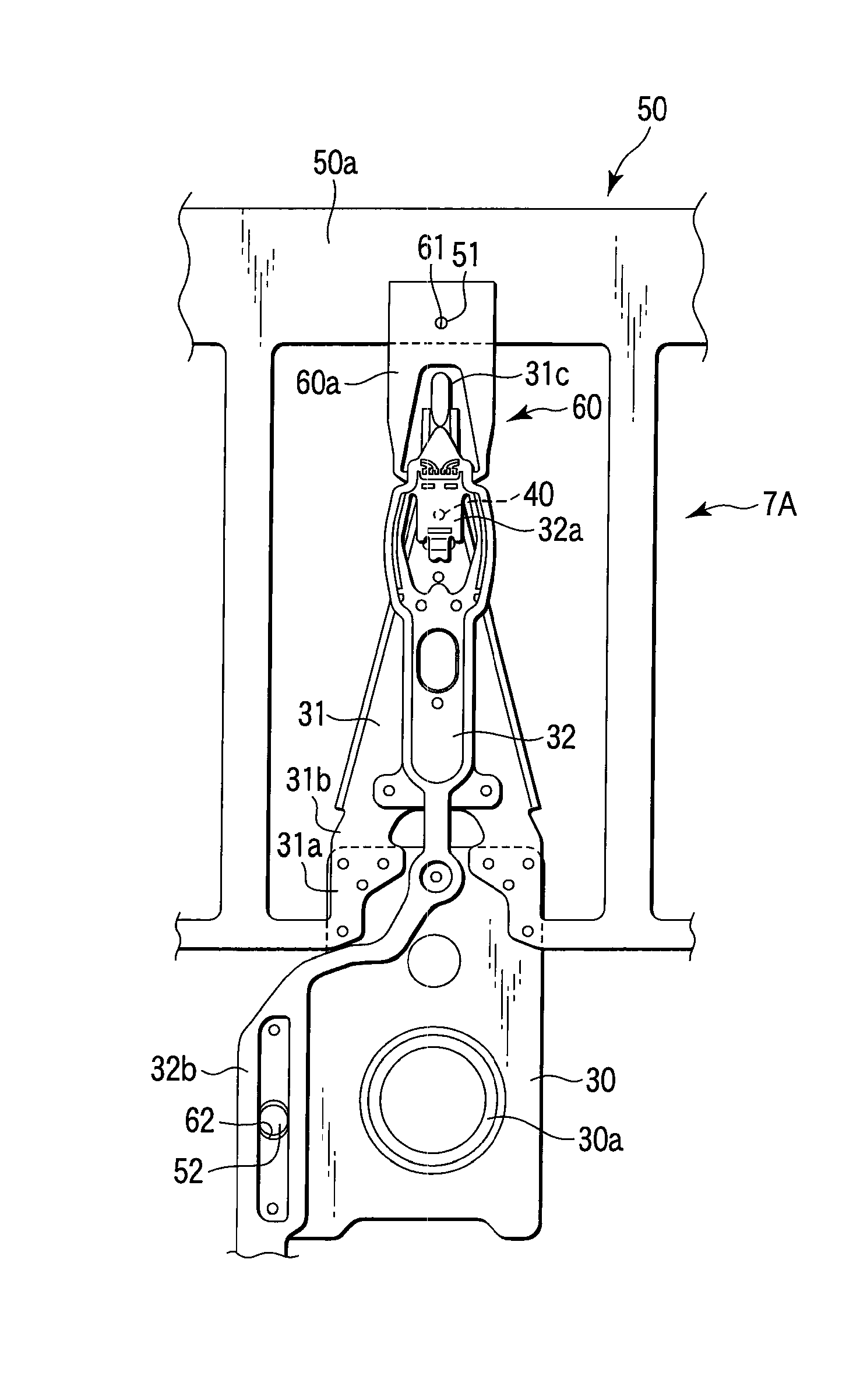
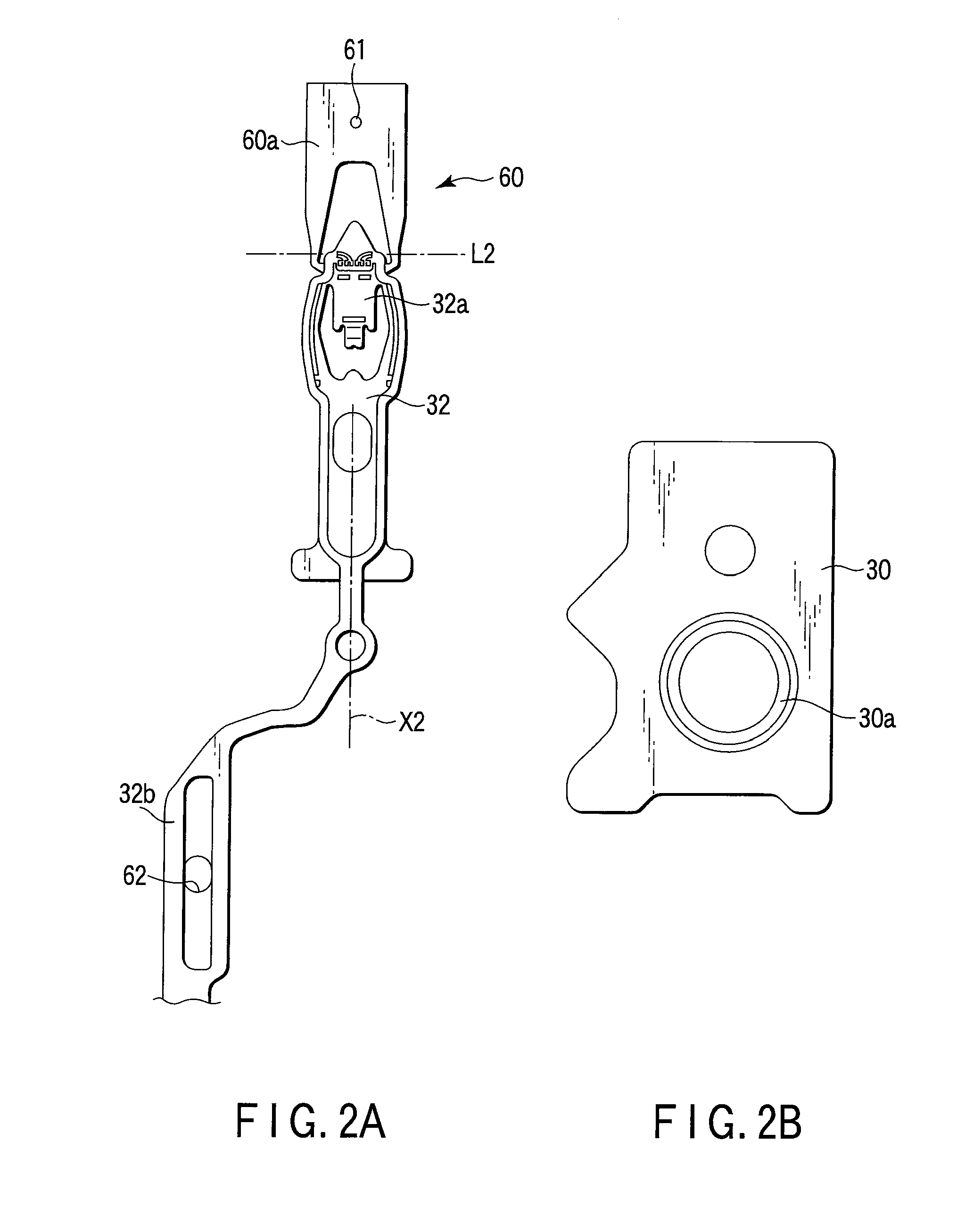
[0054]FIG. 2D shows an example of a magnetic head supporting suspension 7. The suspension 7 comprises a baseplate 30, load beam 31, flexure 32 with conductors, etc. A boss portion 30a of the baseplate 30 is fixed to an arm 6 of the carriage 2 (FIG. 4). FIG. 2C shows a suspension assembly 7A obtained in the process of manufacture of the suspension 7.

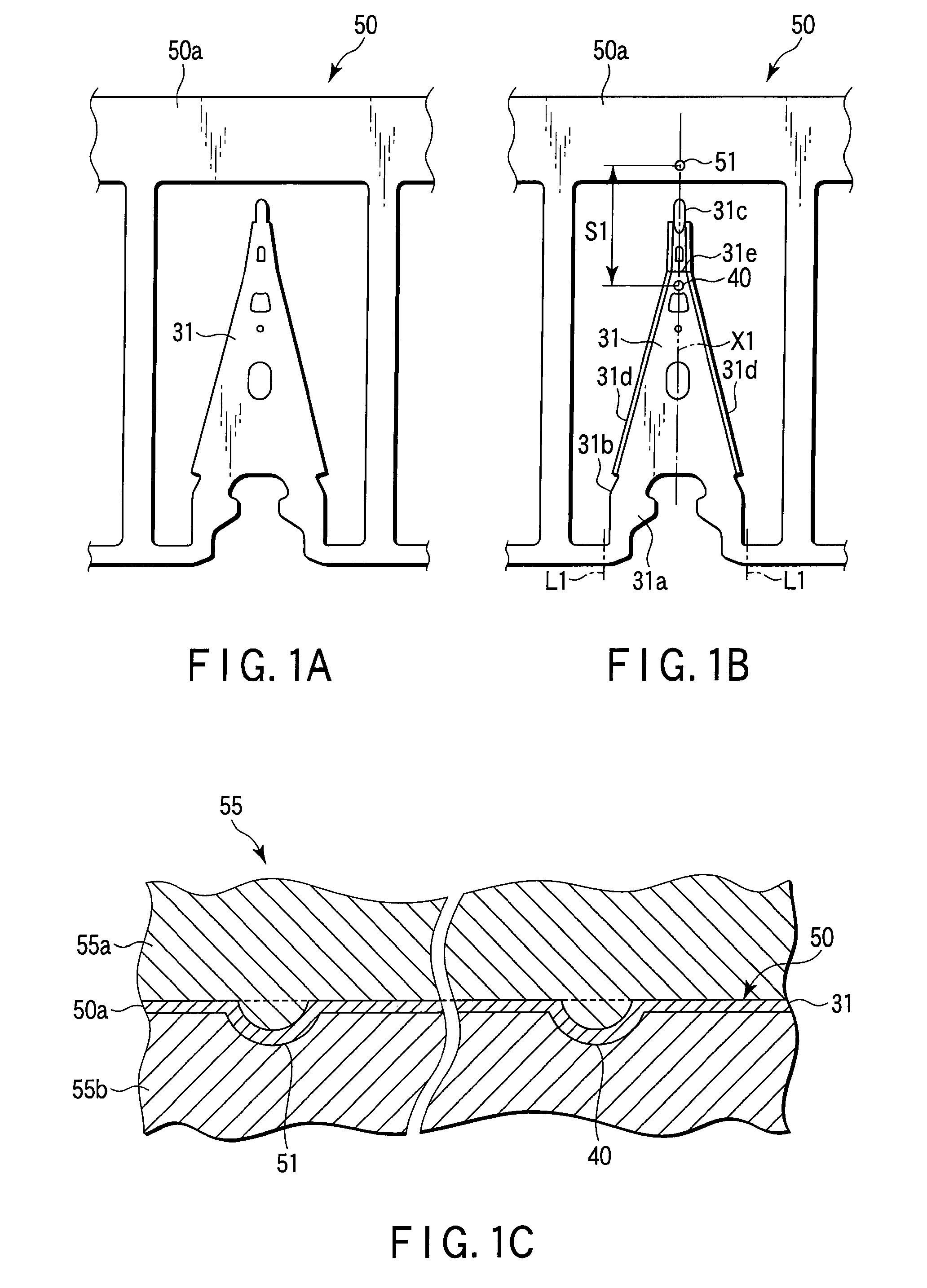
[0055]The load beam 31 comprises a proximal portion 31a fixed to the baseplate 30, hinge portion 31b capable of bending about a lateral axis, and distal end portion 31c. A dimple 40 is disposed near the distal end portion 31c of the load beam 31. The flexure 32 extends along an axis X1 (FIG. 1B) of the load beam 31. A part of the flexure 32 overlaps the load beam 31 and is fixed to the load beam 31 by fixing means, such as laser welding. In FIG. 2D, symbols W1 and W2 designate weld beads between the baseplate 30 and load beam 31 and between ...


PUM

PropertyMeasurementUnit
speedaaaaaaaaaa
heightaaaaaaaaaa
stiffnessaaaaaaaaaa

Abstract

A manufacturing method for a magnetic head supporting suspension includes forming a load beam blank having a load beam with a dimple formed therein, and a frame portion with a positioning part formed therein; and forming a flexure blank having a flexure and a frame portion. A fitting portion in the flexure blank is fittable to the positioning part. An anti-rotation portion is formed on the load beam blank or a member attached to the load beam blank. A receiving portion in the flexure blank is fittable to the anti-rotation portion. The load beam blank and flexure blank are superposed with the positioning part fitted to the fitting portion. The anti-rotation portion is fitted to the receiving portion, and the flexure is fixed to the load beam. The load beam and flexure are thereafter separated from the frame portions.

Description

CROSS-REFERENCE TO RELATED APPLICATIONS[0001]This application is based upon and claims the benefit of priority from prior Chinese Patent Application No. 200910129372.3, filed Mar. 24, 2009, the entire contents of which are incorporated herein by reference.BACKGROUND OF THE INVENTION[0002]1. Field of the Invention[0003]The present invention relates to a manufacturing method for a magnetic head supporting suspension built in an information processing apparatus, such as a personal computer, and a suspension assembly including a load beam blank and flexure blank.[0004]2. Description of the Related Art[0005]FIG. 4 shows a part of a hard disk drive (HDD) 1. A carriage 2 of the disk drive 1 is turned around a shaft 2a by a positioning motor 3, such as a voice coil motor. The motor 3 comprises magnets 4. The carriage 2 comprises a coil portion 5 located near the magnets 4, arms 6, suspensions 7, magnetic heads 8, etc. Arms (or actuators) 6 are fixed to the coil portion 5. The suspensions 7 ...

Claims


Application Information

Patent Timeline
Patent Type & Authority Patents(United States)
IPC IPC(8): G11B5/48G11B21/16
CPCG11B5/4833G11B5/484Y10T29/49025Y10T29/49032
Inventor IKEJI, YOICHIOTAKE, KAZUHIKO
Owner NHK SPRING CO LTD
Learn More