Method for the automatic detection and identification of errors in a balancing machine

Active Publication Date: 2013-10-22
SCHENCK ROTEC GMBH
View PDF32 Cites 6 Cited by
  • Summary
  • Abstract
  • Description
  • Claims
  • Application Information

AI Technical Summary

Benefits of technology

[0009]The object of the invention is to provide a method for the automatic detection and identification of errors in a balancing machine which can be used during normal balancing operation and is not detrimental to the time required for balancing a rotor. Error reports should be reliable and easy for the operator to interpret.
[0012]The method according to the invention makes self-monitoring of a balancing machine possible, making it possible to check during the normal balancing process whether the measurement result is correct. A series of errors which may have occurred can be identified and diagnosed in a single test run. The method according to the invention can be adapted to various operating states and is suitable for identifying a large number of possible error states and diagnosing of the causes thereof. Various signal models, such as constant-frequency vibrations, stochastic signals, and variable-frequency vibrations, can be used for error identification. Therefore, by simultaneously using a plurality of signal models, the most important machine states can be monitored for the absence of errors using the measurement signals detected during balancing. The method is particularly advantageous for monitoring balancing machines which are operated subcritically and in which the run-up and shutdown take several seconds, during which unbalances are not identified. However, the method can also be applied to other balancing machines in which these conditions are not met. With the method according to the invention, symptom-error allocation is still possible, albeit more difficult, in machines which are operated supercritically.
[0013]To increase the reliability of the method according to the invention and monitor a greater number of potential errors, according to a further proposal of the invention, features can additionally be calculated using a process-model-based method and discrepancies can be established by comparison with predetermined normal features of an error-free process.

Problems solved by technology

However, the method can also be applied to other balancing machines in which these conditions are not met.

Method used


Image

  • Method for the automatic detection and identification of errors in a balancing machine
  • Method for the automatic detection and identification of errors in a balancing machine
  • Method for the automatic detection and identification of errors in a balancing machine

Examples


Embodiment Construction

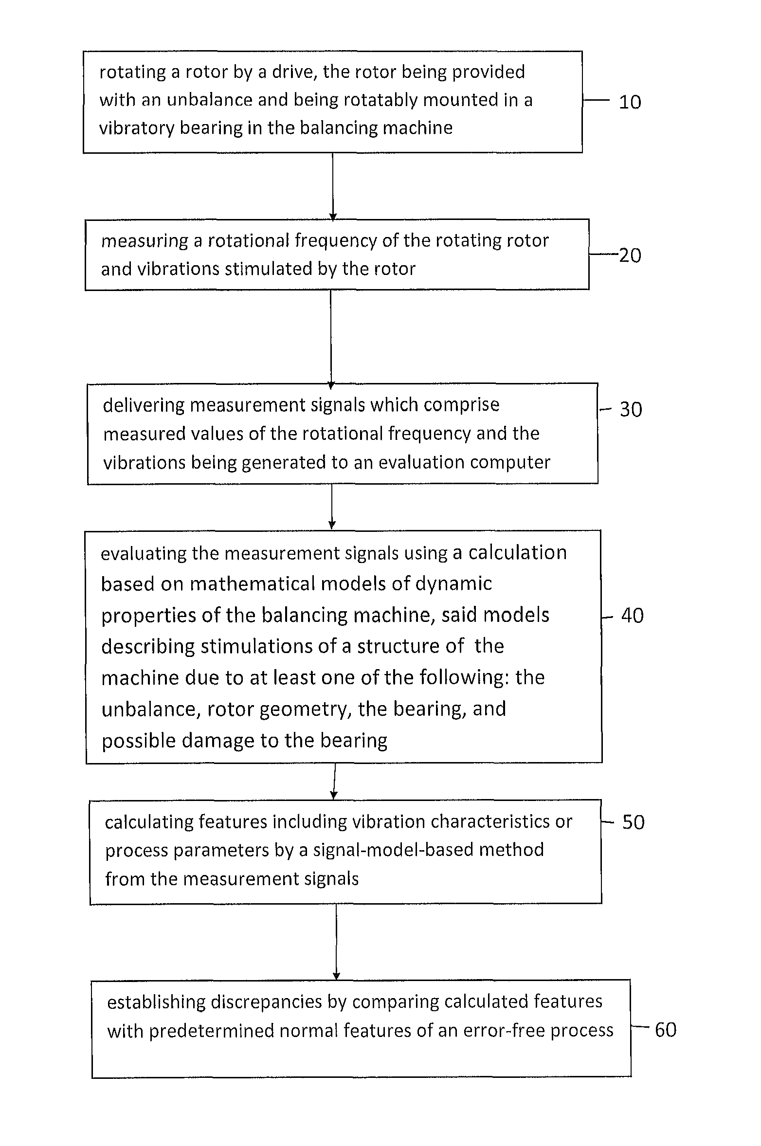
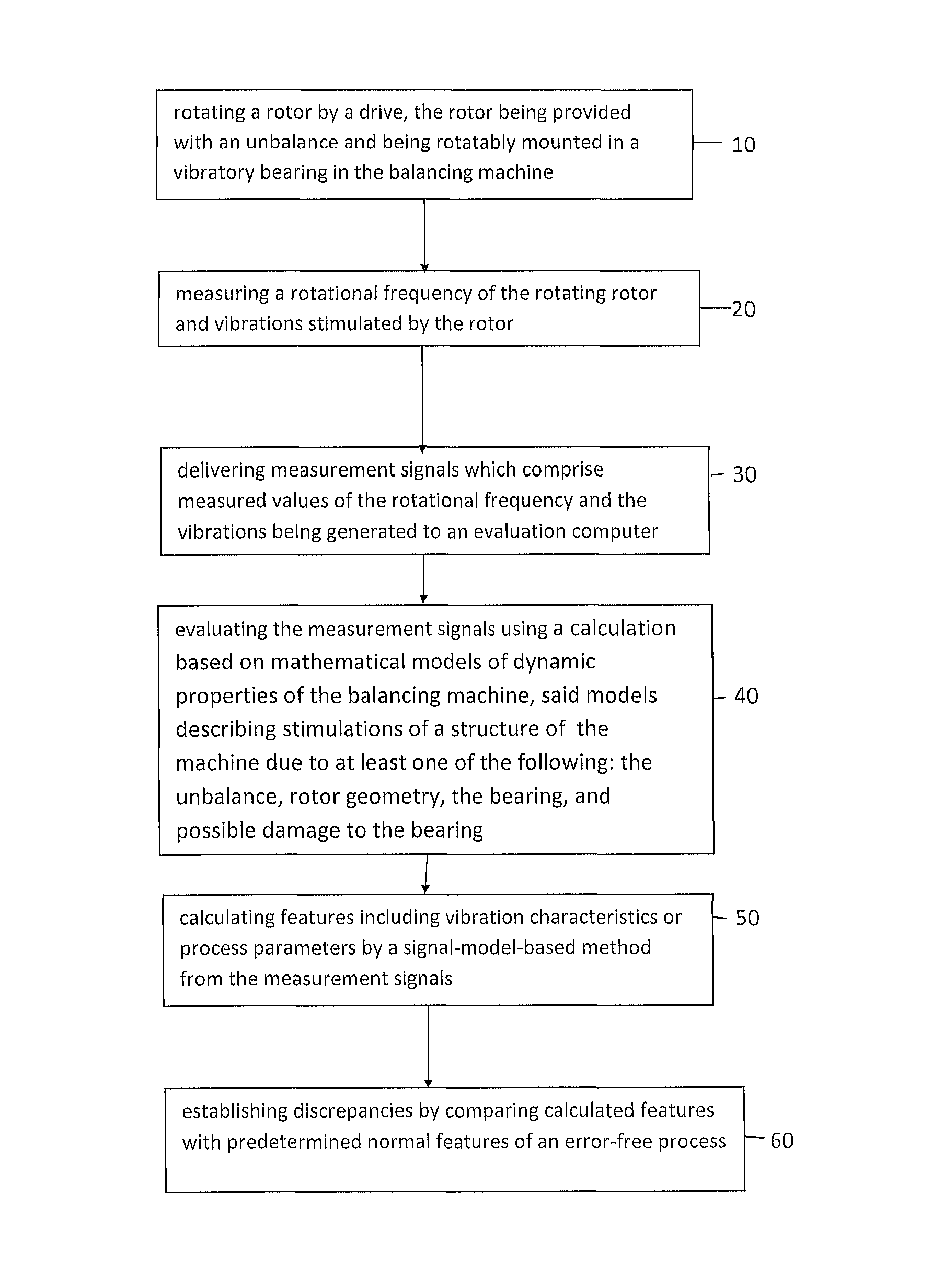
[0019]As shown in the drawing, the invention relates to a method for detection and identification of errors in a balancing machine, in which a first step 10 comprises rotating a rotor by a drive, the rotator being provided with an unbalance and being rotatably mounted in a vibratory bearing in the balancing machine. In a second step 20, a rotational frequency of the rotating rotor and vibrations stimulated by the rotor is measured. In step 30, measurement signals which comprise measured values of the rotational frequency and the vibrations being generated are delivered to an evaluation computer. Step 40 comprises evaluating the measurement signals using a calculation based on mathematical models of dynamic properties of the balancing machine, said models describing stimulations of a structure of the machine due to at least one of the following: the unbalance, rotor geometry, the bearing, and possible damage to the bearing. In step 50, features including vibration characteristics or ...


PUM


Abstract

A method is disclosed for the automatic detection and identification of errors in a balancing machine during operation, in which a rotor provided with an unbalance is rotatably mounted in a vibratory bearing in the balancing machine and is set in rotation by a drive, the rotational frequency of the rotating rotor and the vibrations stimulated by the rotor are measured and measurement signals which comprise the measured values of the rotational frequency and the vibrations are generated and delivered to an evaluation computer. The evaluation calculation is based on mathematical models of the dynamic properties of the balancing machine which describe stimulations of the machine structure due to the unbalance, in particular in the balancing planes, and / or due to the rotor geometry and / or due to the bearing and / or possible damage to the bearing. Features such as vibration characteristics and / or process parameters are calculated by a signal-model-based method from the measurement signals, and discrepancies are established by comparing the calculated features with predetermined normal features of an error-free process.

Description

CROSS REFERENCE TO RELATED APPLICATIONS[0001]Applicants claim priority under 35 U.S.C. §119 of German Application No. 10 2009 038 011.6 filed Aug. 20, 2009.FIELD OF THE INVENTION[0002]The invention relates to a method for the automatic detection and identification of errors in a balancing machine during operation, a rotor provided with an unbalance being rotatably mounted in a vibratory bearing in the balancing machine and being set in rotation by a drive, the rotational frequency of the rotating rotor and the vibrations stimulated by the rotor being measured and measurement signals which comprise the measured values of the rotational frequency and the vibrations being generated and delivered to an evaluation computer.BACKGROUND OF THE INVENTION[0003]Balancing machines are used for balancing rotors. In this process, the mass distribution of a rotor in relation to the axis of rotation thereof is measured and is improved by adding or removing compensating masses until the forces and v...

Claims


Application Information

Patent Timeline
Patent Type & Authority Patents(United States)
IPC IPC(8): G01M1/16
CPCG01M1/22
Inventor BAEHR, JOACHIMISERMANN, ROLFTHELEN, DIETERSCHEITHE, WOLFGANG
Owner SCHENCK ROTEC GMBH
Why Eureka
Try Eureka