
Fluid driven dental handpiece with hydrostatic bearings

a technology of hydrostatic bearings and dental handpieces, applied in the field of fluid, can solve the problems of frequent lubrication and damage to high frequency noise, and achieve the effects of reducing the physical size of the dental handpiece grip, high precision, and economic hardware design

Active Publication Date: 2013-10-22
MAGNESON ALLAN
View PDF22 Cites 6 Cited by
  • Summary
  • Abstract
  • Description
  • Claims
  • Application Information

AI Technical Summary

Benefits of technology

The solution reduces wear, minimizes noise, and maintains a clean environment by using hydrostatic bearings that are energized before turbine rotation, providing a cost-effective and low-maintenance dental handpiece design with improved lubricity and reduced physical size for easier handling.

Problems solved by technology

Dental handpieces widely used today employ bearing systems that utilize expensive precision rolling element bearings that are subject to wear, cause damaging high frequency noise and require frequent lubrication.
The ongoing wear process requires that the user frequently send handpieces out for repair or rebuilding.

Method used


Image

  • Fluid driven dental handpiece with hydrostatic bearings
  • Fluid driven dental handpiece with hydrostatic bearings
  • Fluid driven dental handpiece with hydrostatic bearings

Examples


Embodiment Construction

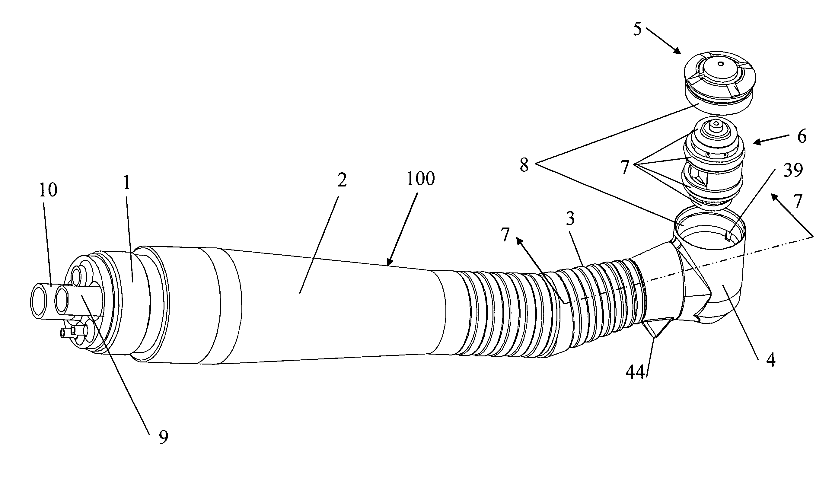
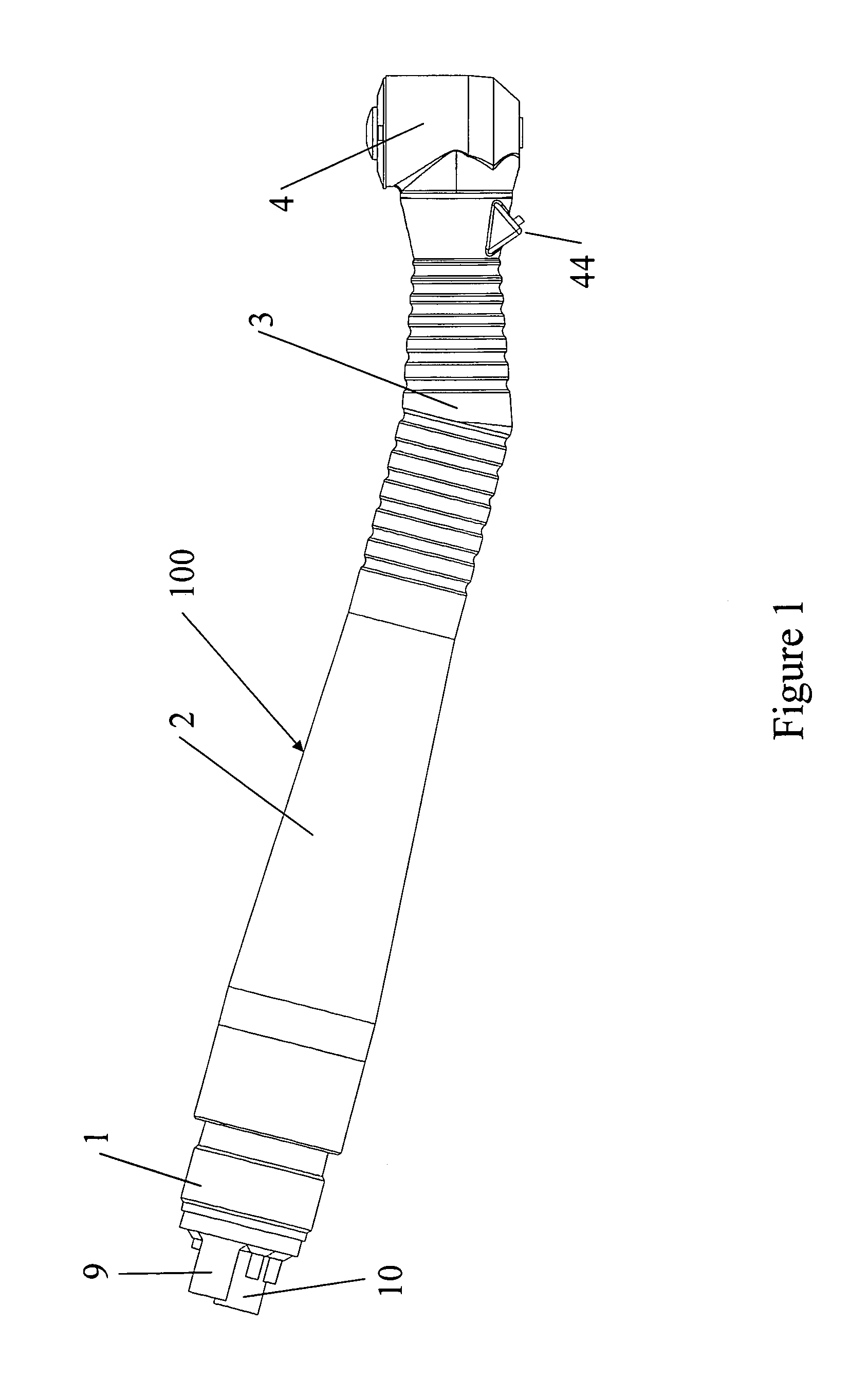
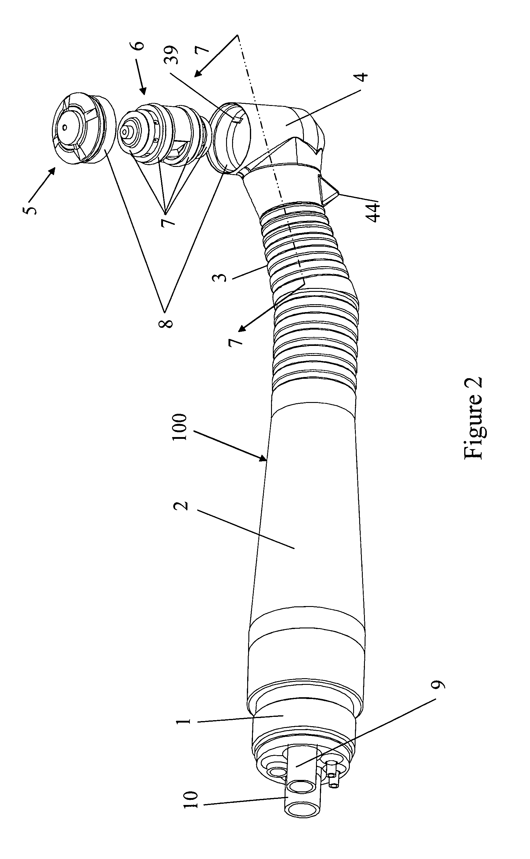
[0035]Referring now to the drawings, wherein like numerals indicate like elements, there is shown in FIG. 1 a dental handpiece 100 in accordance with the present invention. It is understood that the handpiece 100 may be utilized in other applications other than dentistry where a small handpiece is required to provide fluid input and exhaust for a high speed drill. Handpiece 100 includes a connector 1 which may be an ISO 9168-type B connector. Other suitable connectors may be utilized. Handpiece 100 further includes a generally cylindrical handle 2 and a slender elliptically shaped grip 3 and a head 4 which contains a hydrostatic gas bearing cartridge which includes a turbine driven rotor with a chuck for holding a tool as well as the hydrostatic bearings. Also shown in FIG. 1 is the fluid input or compressed air supply tube 9 and exhaust tube 10. Also shown in FIG. 1 is a triangular projection 44 formed on grip 3 which has one or more lights, preferably two spaced lights in the form...


PUM


Abstract

A dental handpiece uses a single airflow input to drive both a rotor and provide a hydrostatic bearing. The fluid flow in the form of compressed air is applied first to the hydrostatic bearings and then subsequently to the turbine blades of the rotor without the use of any moving mechanical parts by the design of the air passageway being more direct for the hydrostatic bearing. This passageway is the form of a manifold insert which may be mounted within the handpiece. The handpiece includes a pair of frusto-conical cages separated by a C-shaped spacer which enables precise fabrication. The frusto-conical ends of the rotor and the mating frusto-conical inner surfaces of the cages are provided with a diamond like carbon coating.

Description

CROSS REFERENCE TO RELATED APPLICATION[0001]This application claims the benefit of the filing date of provisional application No. 61 / 397,531 entitled Fluid Driven Dental Handpiece With Hydrostatic Bearings filed Jun. 11, 2010 by the inventors herein.FIELD OF THE INVENTION[0002]The present invention relates to a fluid, such as compressed air, driven dental handpiece with hydrostatic bearings. More particularly, the present invention relates to a fluid driven dental handpiece with hydrostatic bearings wherein structure is provided to regulate the relative flow to the driving turbine and the hydrostatic bearing structure to provide fluid flow to the bearings prior to activating rotation of the rotor. The term “fluid” as used throughout includes air such as compressed air or any other fluid.BACKGROUND OF THE INVENTION[0003]Dental handpieces for use for drilling, burnishing and other dental operations are widely used today with high speed rotation of a tool held in a head of a dental han...

Claims


Application Information

Patent Timeline
Patent Type & Authority Patents(United States)
IPC IPC(8): A61C1/05
CPCA61C1/05F16C32/0614F16C32/0696F16C2316/13
Inventor MAGNESON, ALLANNEARY, MICHAEL D.OBEID, VICTOR K.
Owner MAGNESON ALLAN
Learn More