External signal detection circuit and real-time clock

a detection circuit and external signal technology, applied in the direction of generating/distributing signals, instruments, pulse techniques, etc., can solve the problems of increased cpu resource occupancy, system performance impairment, and software load, and achieve the effect of high accuracy synchronization of detection

Inactive Publication Date: 2007-02-08
SEIKO EPSON CORP
View PDF2 Cites 0 Cited by
  • Summary
  • Abstract
  • Description
  • Claims
  • Application Information

AI Technical Summary

Benefits of technology

[0018] In this case, the timing signal output portion may include an oscillator portion and a divider portion that produces an output of the oscillation signal by dividing a source oscillation outputted from the oscillator portion. This allows the real-time clock to provide on/off control of the switch portion based on the oscillation signal at any arbitrary frequency. The real-t

Problems solved by technology

If this restricting operation is controlled by a central processing unit (CPU) by using software or an external circuit, load is imposed on the software and the like.
Specifically, this results in increased occupancy of CPU resources.
As a result, system performance is impaired and powe

Method used


Image

  • External signal detection circuit and real-time clock
  • External signal detection circuit and real-time clock
  • External signal detection circuit and real-time clock

Examples


Embodiment Construction

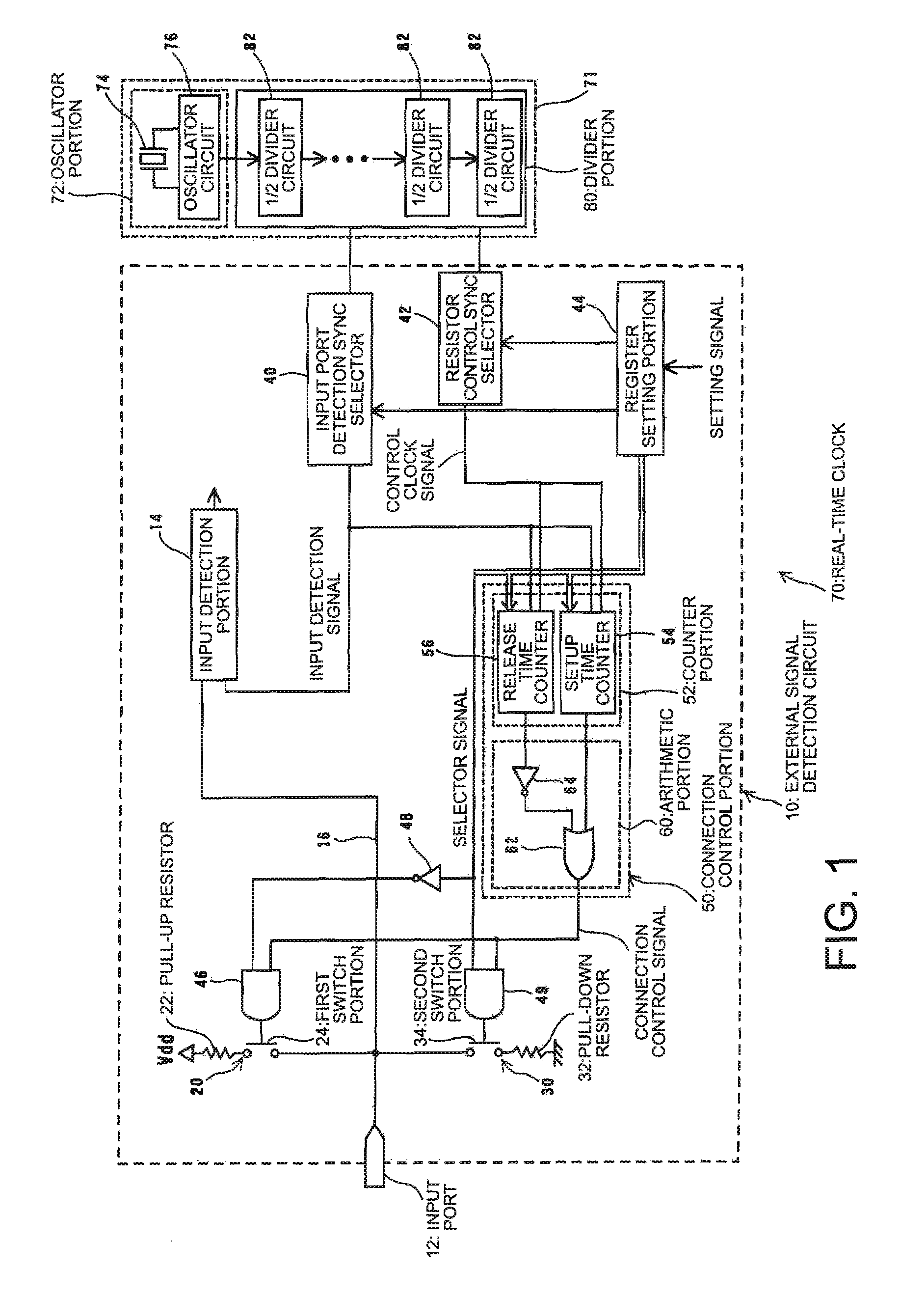
[0024] An external signal detection circuit and a real-time clock according to an embodiment of the invention will be described below. According to the embodiment of the invention, an exemplary embodiment will be described in which the external signal detection circuit is mounted in the real-time clock. FIG. 1 is a block diagram of a principal part of a real-time clock including an external signal detection circuit. An external signal detection circuit 10 includes an input port 12, to which an external signal is inputted. A signal line 16 for guiding the external signal to an input detection portion 14 is connected to the input port 12. An input to the input detection portion 14 is also connected to an input port detection sync selector 40. An input detection signal detecting an input of an external signal to the input detection portion 14 is inputted to the input port detection sync selector 40. The input detection portion 14 may be formed, for example, from a flip-flop circuit.

[0...


PUM


Abstract

An external signal detection circuit includes an input port, to which a first end of a circuit including a pull-up resistor connected in series with a first switch portion is connected, the input port receiving an input of an external signal; an input detection portion connected to the input port for receiving an input of the external signal and an input of an input detection signal that sets a timing for intermittently detecting the input of the external signal; and a connection control portion turning on the first switch portion in time with the timing at which the external signal is detected.

Description

BACKGROUND OF THE INVENTION [0001] 1. Technical Field [0002] The present invention relates to an external signal detection circuit and a real-time clock. [0003] 2. Related Art [0004] A real-time clock is a piezoelectric device that creates digital data, including that indicating time-of-day, date, and the like, from a clock signal. Some of such a real-time clock include an input port of an external signal, in which a signal from an external environment (an external signal) is inputted so that the external signal can be supplied to a central processing unit (CPU), an arithmetic circuit, or the like. The real-time clock herein corresponds to an electronic apparatus mounted with a real-time clock, the electronic device operating in negative logic or positive logic, as the case may be, with a pull-up resistor or a pull-down resistor connected to the input port. [0005]FIG. 3 is diagram illustrating a pull-up resistor and a pull-down resistor connected to an input port. A pull-up resistor...

Claims


Application Information

Patent Timeline
IPC IPC(8): G05F1/00
CPCH03K5/19G06F1/14
Inventor SHIROTORI, TORU
Owner SEIKO EPSON CORP
Why Eureka
Try Eureka