Transformer inrush current suppression apparatus

a transformer inrush current and suppression apparatus technology, applied in the direction of relays, emergency protective arrangements for limiting excess voltage/current, relays, etc., can solve the problems of transformer inrush current, resistor-attached circuit breakers, and many affecting electric power consumers

Active Publication Date: 2013-10-22
KK TOSHIBA
View PDF10 Cites 8 Cited by
  • Summary
  • Abstract
  • Description
  • Claims
  • Application Information

AI Technical Summary

Benefits of technology

[0015]According to an aspect of the present invention, there is provided a transformer inrush current suppression apparatus for suppressing a transformer inrush current of a circuit breaker which makes and breaks connection between an electric power system for a three-phase alternating current, including a power supply and a transformer which converts a three-phase alternating current voltage into a single-phase alternating current voltage, the transformer inrush current suppression apparatus comprising: a transformer side three-phase alternating current voltage measurement unit which measures the three-phase alternating current voltage at a side of the transformer with respect to the circuit breaker; a residual magnetic flux calculation unit which calculates three line-to-line residual magnetic fluxes of the transformer generated after the transformer is detached by the circuit breaker, based on the three-phase alternating current voltage measured by the transformer side three-phase alternating current voltage measurement unit; a power supply side three-phase alternating current voltage measurement unit which measures a three-phase alternating current voltage at a side of the power supply with respect to the circuit breaker; a stable-state magnetic flux calculation unit which calculates three line-to-line stable-state magnetic fluxes of the transformer, based on the three-phase alternating current voltage measured by the power supply side three-phase alternating current voltage measurement unit; a phase determination unit which determines a phase in which phases of the three line-to-line stable-state magnetic fluxes calculated by the stable-state magnetic flux calculation unit are respectively the same in polarity as phases of the three line-to-line residual magnetic fluxes calculated by the residual magnetic flux calculation unit; and a closing unit which closes the circuit breaker in the phase determined by the phase determination unit.

Problems solved by technology

When such a large transformer inrush current flows, the system voltage fluctuates, and when this voltage fluctuation is large, this many affect electric power consumers.
However, the above methods for suppressing transformer inrush currents have the following problems.
In the method for suppressing a transformer inrush current using a resistor-attached circuit breaker, there is a problem in that it is necessary to add a resistor-attached circuit breaker to an ordinary circuit breaker.
For example, in the method for measuring the residual magnetic flux and controlling the closing phase of the circuit breaker, the method for controlling the three-phase transformer used for a power system cannot be directly applied to the Scott connection transformer.

Method used


Image

  • Transformer inrush current suppression apparatus
  • Transformer inrush current suppression apparatus
  • Transformer inrush current suppression apparatus

Examples


first embodiment

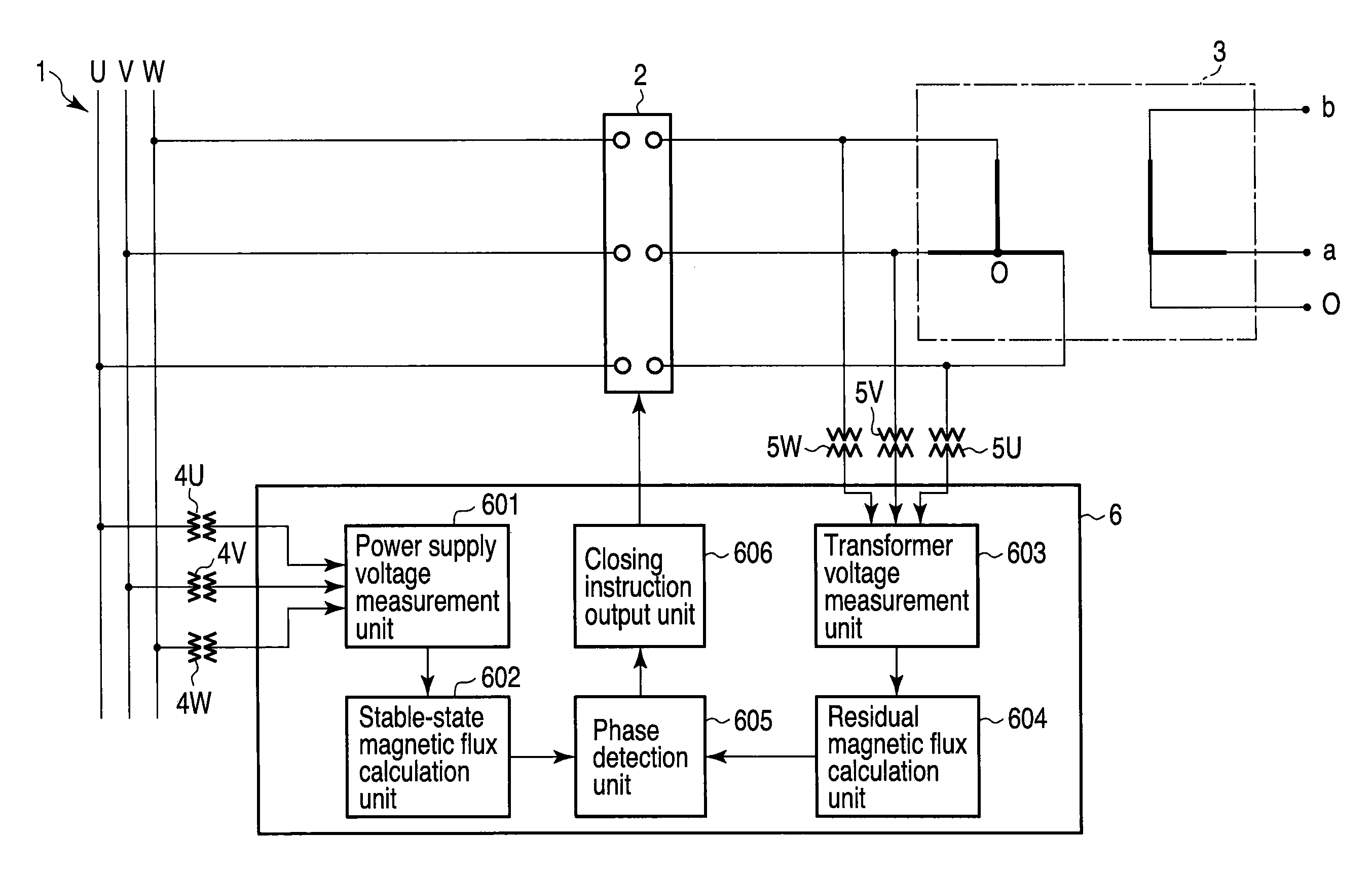
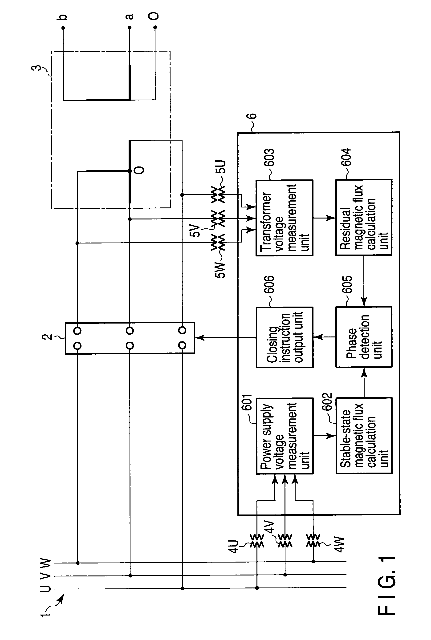
[0054]FIG. 1 is a block diagram illustrating a configuration of an electric power system including a transformer inrush current suppression apparatus 6 according to the first embodiment of the present invention. In the following drawings, the same portions are denoted with the same reference numerals, and detailed description thereof is omitted. Different portions will be mainly explained. Likewise, overlapped explanations are omitted in the subsequent embodiments.

[0055]The electric power system according to the present embodiment includes a power supply busbar 1, a circuit breaker 2, a Scott connection transformer 3, power supply voltage detectors 4U, 4V, 4W for three phases arranged in the power supply busbar 1, transformer primary side voltage detectors 5U, 5V, 5W for three phases arranged at the primary side of the Scott connection transformer 3, and a transformer inrush current suppression apparatus 6.

[0056]The power supply busbar 1 is a busbar for an electric power system incl...

first modification

of First Embodiment

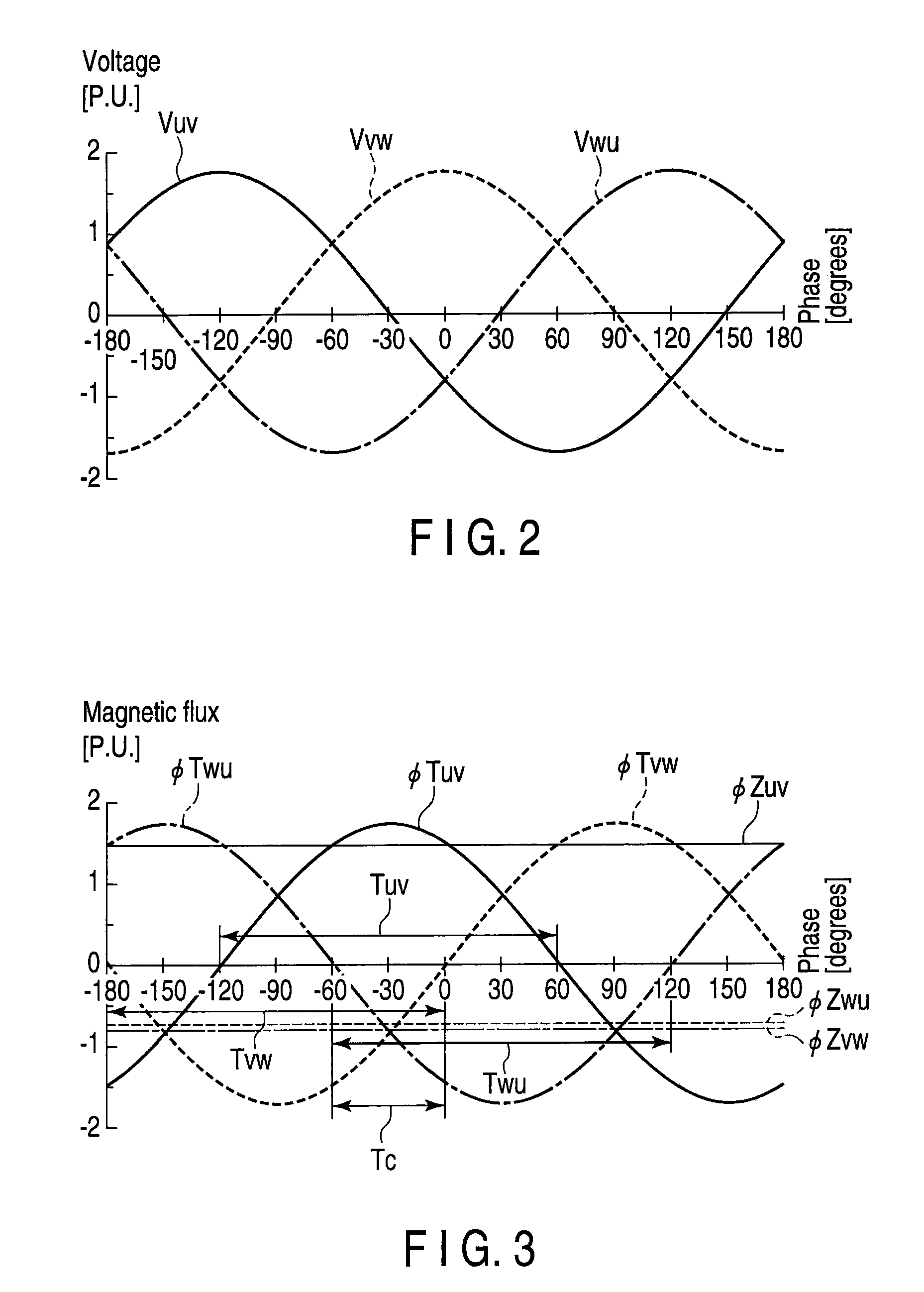
[0087]In the first embodiment, the closing target phase region Tc is detected based on the stable-state magnetic fluxes φuv, φvw, φwu calculated by the stable-state magnetic flux calculation unit 602. In contrast, a transformer inrush current suppression apparatus 6 according to this modification is configured such that the closing target phase region Tc is detected based on phase voltages or line-to-line voltages measured by the power supply voltage measurement unit 601.

[0088]The transformer inrush current suppression apparatus 6 detects, as the closing target phase region Tc, a phase section in which the polarities of the phase voltages or the line-to-line voltages measured by the power supply voltage measurement unit 601 are respectively the same as the polarities of the residual magnetic fluxes φZuv, φZvw, φZwu between respective lines calculated by the residual magnetic flux calculation unit 604.

[0089]In this case, the phase difference between the line-to-lin...

second modification

of First Embodiment

[0094]A transformer inrush current suppression apparatus 6 according to this modification is configured to output a closing instruction as follows.

[0095]The phase detection unit 605 detects a line-to-line having the largest residual magnetic flux from among the residual magnetic fluxes φZuv, φZvw, φZwu calculated by the residual magnetic flux calculation unit 604. A voltage zero point is detected at which the polarity of the voltage of the detected line-to-line changes from the same polarity to the opposite polarity with respect to the residual magnetic flux of the line-to-line (the largest residual magnetic flux). The phase detection unit 605 outputs the detected voltage zero point to the closing instruction output unit 606. The closing instruction output unit 606 outputs a closing instruction to the circuit breaker 2 upon adopting the voltage zero point detected by the phase detection unit 605 as a closing phase target.

[0096]According to this modification, the f...


PUM


Abstract

Inrush current suppression apparatus for suppressing a transformer inrush current including a transformer side voltage measurement unit which measures a voltage at a side of a transformer, a residual magnetic flux calculation unit which calculates three line-to-line residual magnetic fluxes, a power supply side voltage measurement unit which measures a voltage at a side of a power supply, a stable-state magnetic flux calculation unit which calculates three line-to-line stable-state magnetic fluxes, based on the voltage at the side of the power supply, a phase determination unit which determines a phase in which phases of the three line-to-line stable-state magnetic fluxes are respectively the same in polarity as phases of the three line-to-line residual magnetic fluxes, and a closing unit which closes the circuit breaker in the phase determined by the phase determination unit.

Description

CROSS-REFERENCE TO RELATED APPLICATIONS[0001]This application is based upon and claims the benefit of priority from prior Japanese Patent Application No. 2010-017263, filed Jan. 28, 2010, the entire contents of which are incorporated herein by reference.BACKGROUND OF THE INVENTION[0002]1. Field of the Invention[0003]The present invention relates to a transformer inrush current suppression apparatus for suppressing a transformer inrush current which occurs when a circuit breaker is closed.[0004]2. Description of the Related Art[0005]When a transformer is energized without any load by being connected to a power supply while there is residual magnetic flux in a transformer core, a large transformer inrush current is known to flow. The magnitude of this transformer inrush current is several times larger than the rated load current of the transformer. When such a large transformer inrush current flows, the system voltage fluctuates, and when this voltage fluctuation is large, this many a...

Claims


Application Information

Patent Timeline
Patent Type & Authority Patents(United States)
IPC IPC(8): H01H47/00
CPCH02H9/002H01H9/563H02H7/04
Inventor UDAGAWA, KEISUKEKOSHIZUKA, TADASHIMARUYAMA, SHIROSAITO, MINORUNAGAYAMA, NORIYUKI
Owner KK TOSHIBA
Why Eureka
Try Eureka