Horizontal synchronization signal detection system and method

a horizontal synchronization and signal detection technology, applied in television systems, pulse automatic control, color burst signal generation/insertion, etc., can solve the problems of reducing the accuracy of hsync detection, difficult hsync detection, and frequent change of input video signal level, so as to achieve accurate detection of horizontal synchronization signal position

Inactive Publication Date: 2013-10-22
SUNPLUS TECH CO LTD
View PDF4 Cites 2 Cited by
  • Summary
  • Abstract
  • Description
  • Claims
  • Application Information

AI Technical Summary

Benefits of technology

[0015]The object of the present invention is to provide a horizontal synchronization signal detection system and method for accurately detecting the position of a horizontal synchronization signal.

Problems solved by technology

However, such an Hsync detection can affect the level of the input video signal 10 due to the noise interference of the system of FIG. 2, and the level or amplitude of the Hsync pulse 12 is also changed, resulting in that the accuracy of the Hsync detection is decreased.
In addition, the signal transmission may cause the deformation or loss of the input video signal, which further makes the Hsync detection more difficult.
The above schemes use a threshold as a level comparison signal of Hsync detection, but the level of an input video signal is frequently changed due to the noise interference.
Therefore, the level comparison schemes in the existing techniques are possibly unable to accurately detect Hsync signal or even unable to detect any Hsync signal, or erroneously take other portions of an input video signal as the Hsync signal.

Method used


Image

  • Horizontal synchronization signal detection system and method
  • Horizontal synchronization signal detection system and method
  • Horizontal synchronization signal detection system and method

Examples


Embodiment Construction

[0028]Reference will now be made in detail to present embodiments of the present invention, examples of which are illustrated in the accompanying drawings. Wherever possible, the same reference numbers will be used throughout the drawings to refer to the same or like parts.

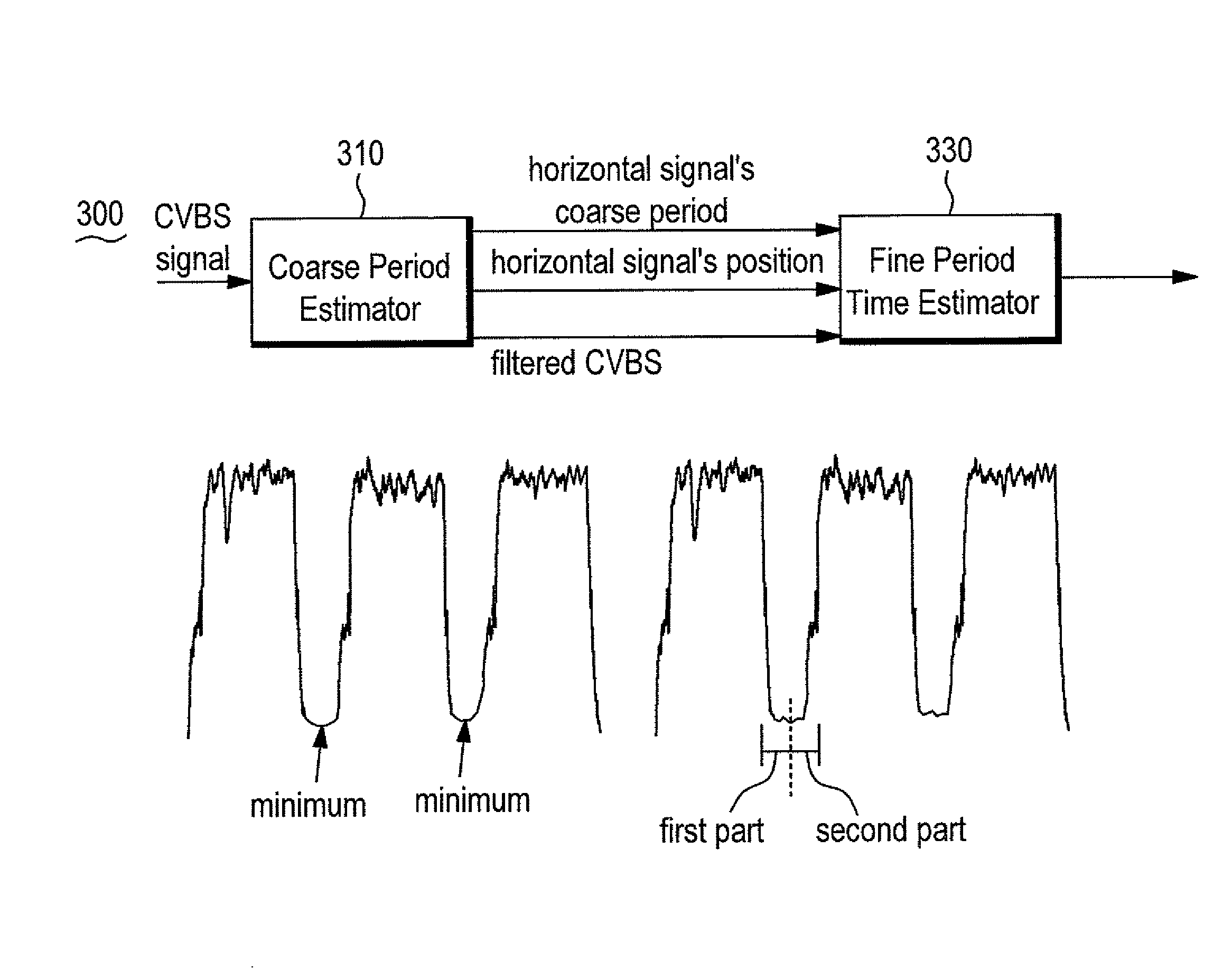
[0029]The invention relates to a horizontal synchronization signal detection system and method. FIG. 3 is a schematic diagram of the horizontal synchronization detection system 300 for describing its detection principle in accordance with a preferred embodiment of the invention. In FIG. 3, the system 300 includes a coarse period estimator 310 and a fine period time estimator 330.

[0030]The coarse period estimator 310 receives the CVBS signal and, due to the horizontal synchronization signal of the CVBS signal being featured with having periodicity and minimum value, estimates the minimum value and labels the corresponding position in each period, so as to calculate a coarse period of a horizontal synchronization si...


PUM


Abstract

A horizontal synchronization signal detection system includes a coarse period estimator and a fine period time estimator. The coarse period estimator estimates a minimum value and corresponding position of each period of a CVBS signal to calculate a coarse period of a horizontal synchronization signal. The fine period time estimator divides the horizontal synchronization signal into a first part and a second part so as to generate a first sum and a second sum by adding signals of the first part and the second part, and detects a middle point of the horizontal synchronization signal when the first sum equals the second sum. The steps of fine-tuning the coarse period to generate a fine-tuned coarse period, extracting the horizontal synchronization signal according to the fine-tuned coarse period, and determining whether the first sum is equal to the second sum are repeatedly executed until the first sum equals the second sum.

Description

CROSS REFERENCE TO RELATED APPLICATION[0001]This application claims the benefits of the Taiwan Patent Application Serial Number 100109151, filed on Mar. 17, 2011, the subject matter of which is incorporated herein by reference.BACKGROUND OF THE INVENTION[0002]1. Field of the Invention[0003]The present invention relates to the technical field of timing synchronization and, more particularly, to a horizontal synchronization signal detection system and method.[0004]2. Description of Related Art[0005]Color video burst signal (CVBS) is an NTSC-defined television (TV) transmission signal. FIG. 1 is a schematic view illustrating a typical analog CVBS signal 10. As shown in FIG. 1, the analog CVBS signal 10 includes a front porch 11, a horizontal synchronization (Hsync) pulse 12, a back porch 13, a color video burst 13a, and an active line 14. The Hsync pulse 12 indicates the start portion for each line of the video information. Each Hsync pulse 12 starts with the front porch 11 and ends at...

Claims


Application Information

Patent Timeline
Patent Type & Authority Patents(United States)
IPC IPC(8): H04N5/10H04N5/06
CPCH04N5/08H04N17/00
Inventor YANG, FANG-MING
Owner SUNPLUS TECH CO LTD
Why Eureka
Try Eureka