Image forming apparatus

a technology of forming apparatus and forming surface, which is applied in the direction of electrographic process apparatus, printing, instruments, etc., can solve the problems of increasing the amount of irregular reflected light in toner pattern detection, lowering the gloss of a base surface due to a difference in reflectivity between sheet surfaces,

Active Publication Date: 2013-10-22
CANON KK
View PDF60 Cites 3 Cited by
  • Summary
  • Abstract
  • Description
  • Claims
  • Application Information

AI Technical Summary

Benefits of technology

[0011]The present invention provides an image forming apparatus capable of ensuring a sufficient difference between amounts of light reflected from a base such as an image carrier or a transfer material and from a toner pattern in the detection of the toner pattern for registration correction control by an optical detection unit.
[0015]According to the present invention, in the detection of a toner pattern for registration correction control by the optical detection unit, it is possible to ensure a sufficient difference between amounts of light reflected from a base such as an image carrier or a transfer material and from the toner pattern.

Problems solved by technology

When an intermediate transfer belt or a photosensitive drum is employed as the base, the gloss of a surface of the base is lowered due to long-term use and contamination thereof.
When a sheet is employed as the base, the presence of a variety of sheet types (colored paper, glossy paper, or the like) results in a difference in reflectivity between sheet surfaces.
With increase in the amount of light irradiated from the sensor, however, an amount of irregularly reflected light increases in the toner pattern detection, especially, in the detection of a color toner pattern.
As a result, a failure in the toner pattern detection can be caused, resulting in a fear that a defect image is printed out.
In a regular reflective optical sensor, optical axis misalignment occurs due to a mounting error of the sensor to an apparatus, an assembly error of the sensor, a variation in characteristics of optical parts of the sensor, or other reasons.
If the amount of light received by the sensor in the toner pattern detection changes to increase, a reduction is caused in the difference between the amounts of light received by the sensor from the base and from the toner pattern, making it difficult to discriminate between the base and the toner pattern.
This may result in a failure in toner pattern detection, producing a fear that an image entailing an image position displacement is printed out.

Method used


Image

  • Image forming apparatus
  • Image forming apparatus
  • Image forming apparatus

Examples


first embodiment

[0032]First, with reference to FIGS. 1 to 6, an image forming apparatus according to the present invention will be explained.

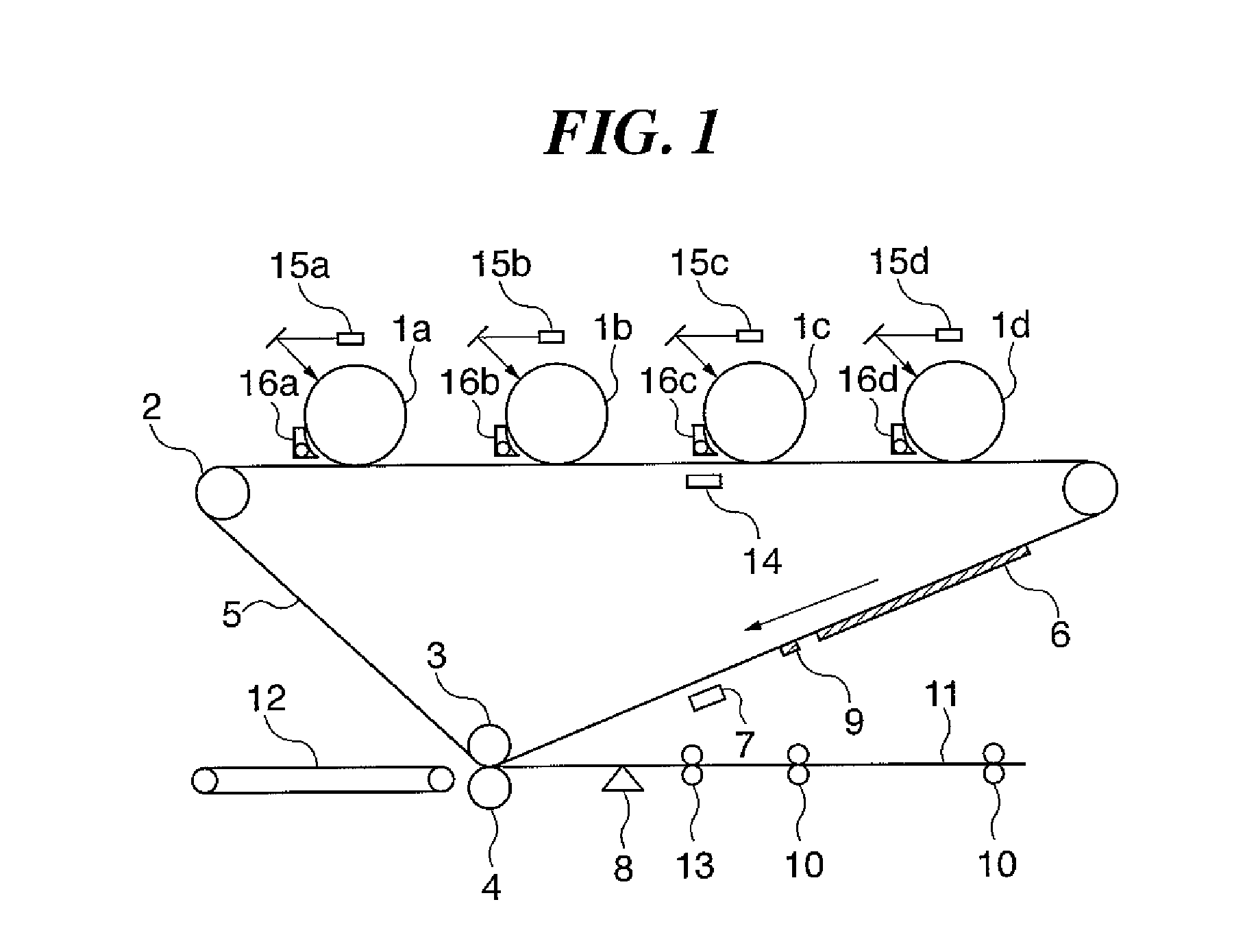
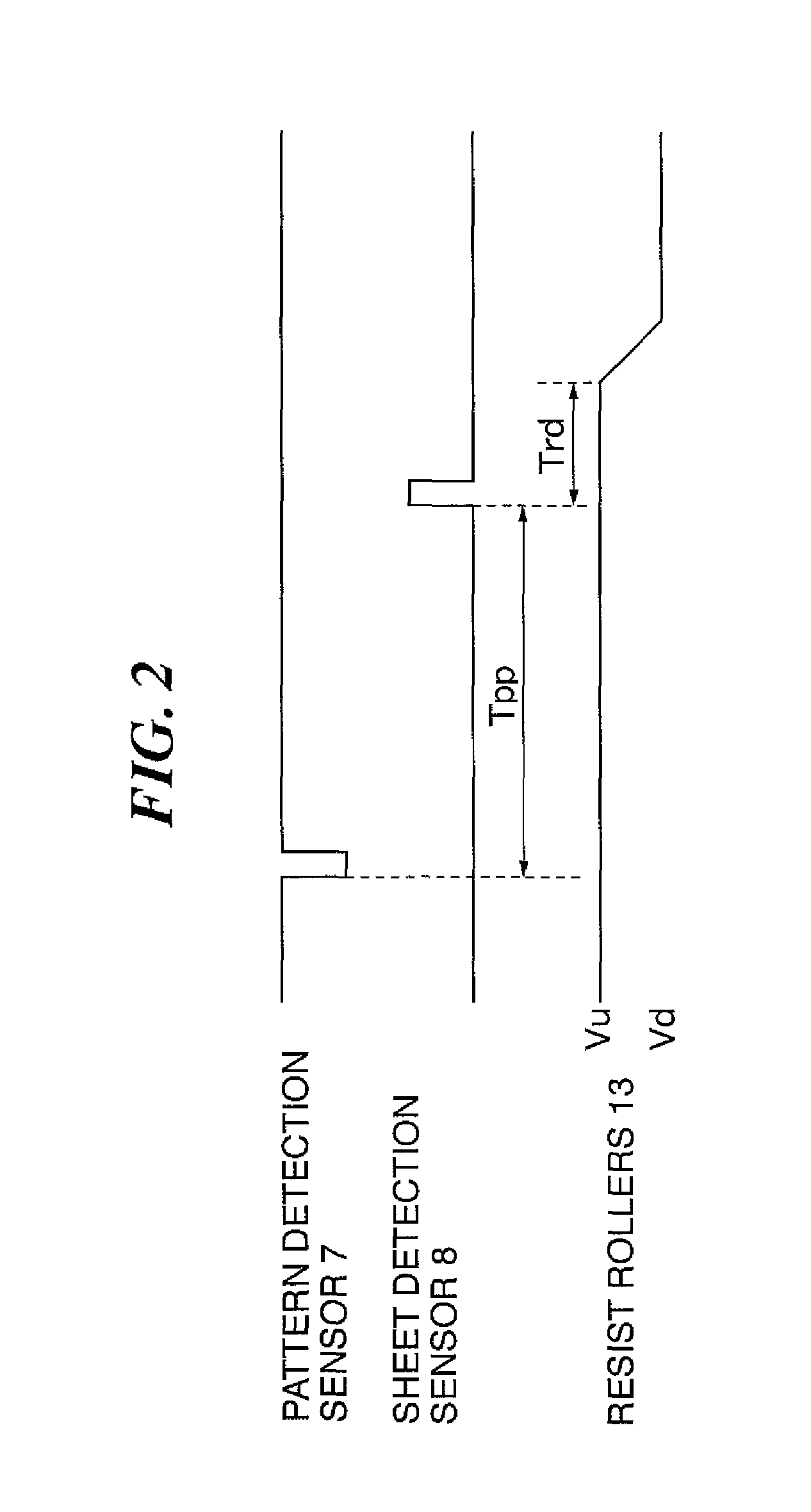
[0033]FIG. 1 is a schematic view for explaining the construction of an image forming section of an image forming apparatus according to the first embodiment, and FIG. 2 is a timing chart for explaining basic image-position correction control performed by the image forming apparatus shown in FIG. 1. FIG. 3 is a block diagram schematically showing a control circuit for implementing the image-position correction control, and FIG. 4 is a graph showing a relation between amounts of light irradiated from and received by a pattern detection sensor at a maximum toner pattern density. FIG. 5 is a graph showing a relation between the toner pattern density and the amount of light received by the pattern detection sensor, the relation being observed when the amount of light irradiated from an LED light source is at a maximum. FIG. 6 is a graph showing a relation for each ...

second embodiment

[0059]Next, with reference to FIGS. 7 to 10, an image forming apparatus according to the present invention will be explained.

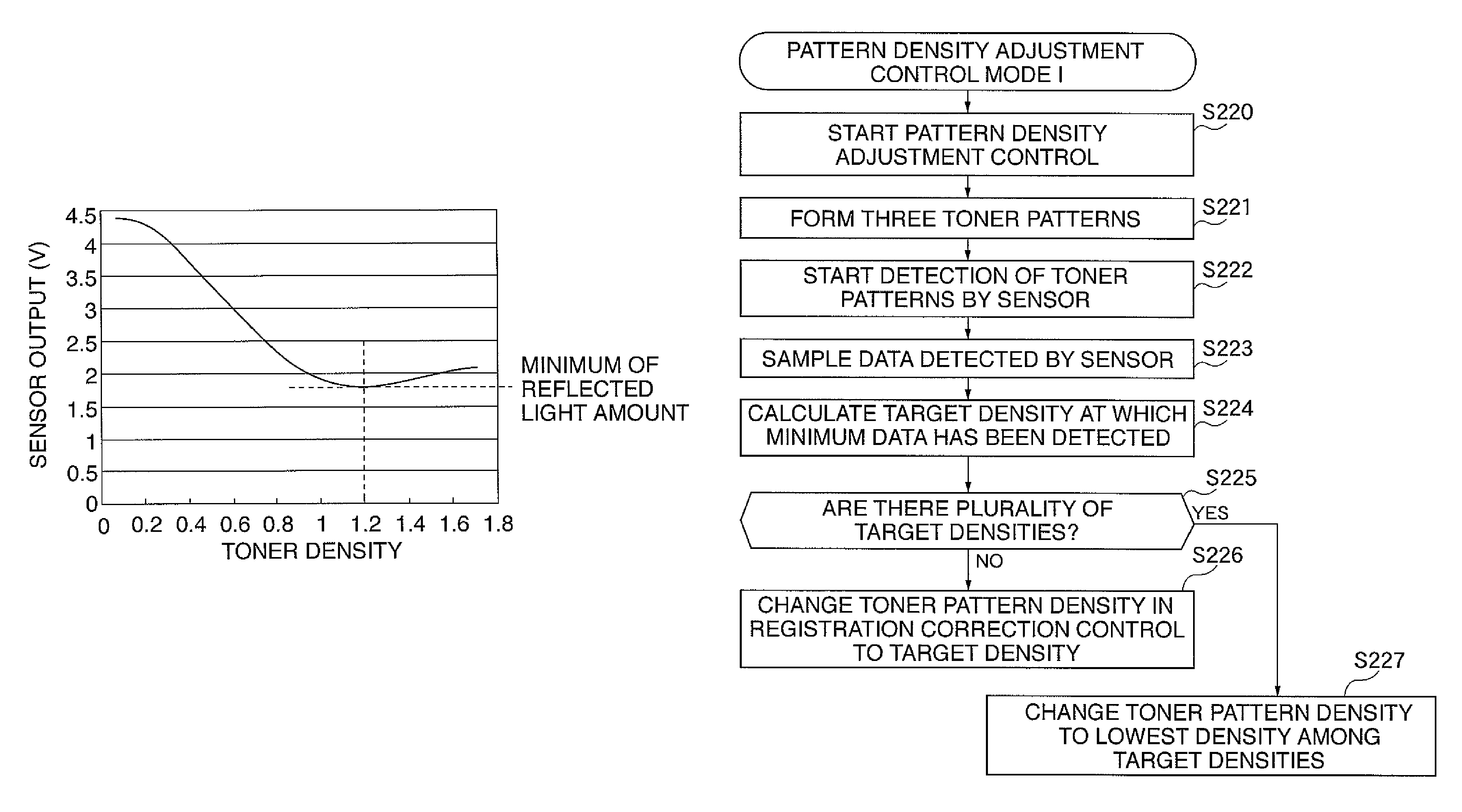
[0060]FIG. 7 is a block diagram for schematically showing a control circuit of the image forming apparatus of the second embodiment for implementing registration correction control. FIG. 8 is a graph showing a change in received light amount in the detection of toner patterns with five different density levels by the pattern detection sensor. FIG. 9 is a flowchart for explaining an exemplar operation in pattern density adjustment control mode I, and FIG. 10 is a flowchart for explaining an exemplar operation in pattern density adjustment control mode II. It should be noted that the image forming section of the image forming apparatus is the same as that of the first embodiment having been described with reference to FIG. 1, and therefore, explanations thereof will be omitted. The basic control for image-position (registration) correction is the same as that of...

third embodiment

[0090]In the following, with reference to FIGS. 11 to 14, an image forming apparatus according to the present invention will be described.

[0091]FIG. 11 is a block diagram for schematically showing a control circuit of the image forming apparatus of the third embodiment for implementing the registration correction control, and FIG. 12 is a flowchart for explaining an exemplar operation in a pattern density real-time control mode I. FIG. 13 is a graph showing a relation between the drive current of the pattern detection sensor and the toner pattern density, and FIG. 14 is a flowchart for explaining an exemplar operation in a pattern density real-time control mode II. It should be noted that the image forming section of the image forming apparatus is the same as that described with reference to FIG. 1 in the first embodiment, and explanations thereof will be omitted. The basic control for image-position (registration) correction is also the same as that described with reference to FIG....


PUM


Abstract

An image forming apparatus capable of ensuring a sufficient difference between amounts of light reflected from a base such as a transfer material and from a toner pattern in the detection of the toner pattern for registration correction control by a reflective optical sensor. The image forming apparatus includes a pattern generator for generating a toner pattern, a pattern detection sensor for detecting the toner pattern formed on the intermediate transfer belt, a pattern density decider for determining the density of the toner pattern that makes the amount of light received by the sensor in detection of the toner pattern equal to or less than a predetermined value.

Description

BACKGROUND OF THE INVENTION[0001]1. Field of the Invention[0002]The present invention relates to an image forming apparatus for electrophotographic system-based image formation, such as a printer, copy machine, facsimile, or the like.[0003]2. Description of the Related Art[0004]For registration correction control of an image forming apparatus, a regular reflective optical sensor is generally used, which includes an LED light source (irradiation optical source) and a PD element (light receiving element). The optical sensor is for detecting a toner pattern for registration correction control. The toner pattern is formed on a base such as a sheet or an image carrier, the image carrier being an intermediate transfer belt, a photosensitive drum, or the like. In the detection of a toner pattern by the sensor, amounts of light reflected by the base and by the toner pattern are detected and a difference therebetween is utilized for position detection. Resultant position information is emplo...

Claims


Application Information

Patent Timeline
Patent Type & Authority Patents(United States)
IPC IPC(8): G03G15/00
CPCG03G15/0131G03G15/5058G03G2215/00042G03G2215/00059G03G2215/0161
Inventor NAKAZATO, JUNKODAMA, HIROKAZUTAKEZAWA, SATORU
Owner CANON KK
Why Eureka
Try Eureka