Multilayer backing absorber for ultrasonic transducer

a technology of ultrasonic transducers and backing absorbers, which is applied in the direction of mechanical vibration separation, instruments, paper/cardboard containers, etc., can solve the problems of insufficient structure and technique, deficient structure and technique in several aspects, and difficult control of pressure application in a constant and reproducible manner

Active Publication Date: 2013-10-29
MEASUREMENT SPEC
View PDF16 Cites 71 Cited by
  • Summary
  • Abstract
  • Description
  • Claims
  • Application Information

AI Technical Summary

Benefits of technology

[0009]According to an aspect of the present invention, a multilayer backing absorber for ultrasonic transducers operative in thickness mode for example has an acoustic impedance and absorption adapted according to a given sensitivity and bandwidth. The novel multilayer backing absorber provides for transducer performance with a smooth frequency response curve without many spurious peaks.

Problems solved by technology

However, such structures and techniques are deficient in several aspects.
Because the metal surface is not ideally flat and microscopic roughness exists, the actual or real contacting area represents a small fraction of the total surface area, and ultrasonic waves propagate through mostly in these small spots where absorption of acoustic waves takes place.
However, such a structure does not provide appropriate absorption.
However, it is difficult to control the application of pressure in a constant and reproducible manner within this environment.
For example, when applying high pressure, metal is usually fatigued and pressure decreases in time, thereby causing the absorption to decrease over time.
A further problem with the known multilayer backing absorber concerns the difficulty in designing the pressurizing structure.
Piezoelectric materials such as PZT or crystal are brittle and easily broken by the applied pressure, and yet multiple layers of metallic foils have to be pressed against the piezoelectric layer.
It is difficult to design such a structure, particularly when the size of the piezoelectric layer is thin (less than 0.5 mm) and large (more than 5 mm).
Furthermore, the pressurizing structure, which typically includes screws and a holder, make the device bulky.
Still further, the absorption and impedance cannot simply be designed to a specified value.
Backing absorbers are relatively difficult to manufacture and control the absorption and acoustic impedance of these devices.
Such processes are difficult to control.
Such problems of difficulty in design, reproducibility and reliability are commonly seen for any absorber including the aforementioned examples.

Method used


Image

  • Multilayer backing absorber for ultrasonic transducer
  • Multilayer backing absorber for ultrasonic transducer
  • Multilayer backing absorber for ultrasonic transducer

Examples


Embodiment Construction

[0025]Reference will now be made in detail to the present exemplary embodiments of the invention, examples of which are illustrated in the accompanying drawings. Wherever possible, the same reference numbers will be used throughout the drawings to refer to the same or like parts.

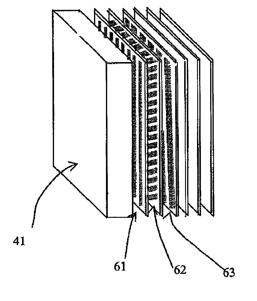
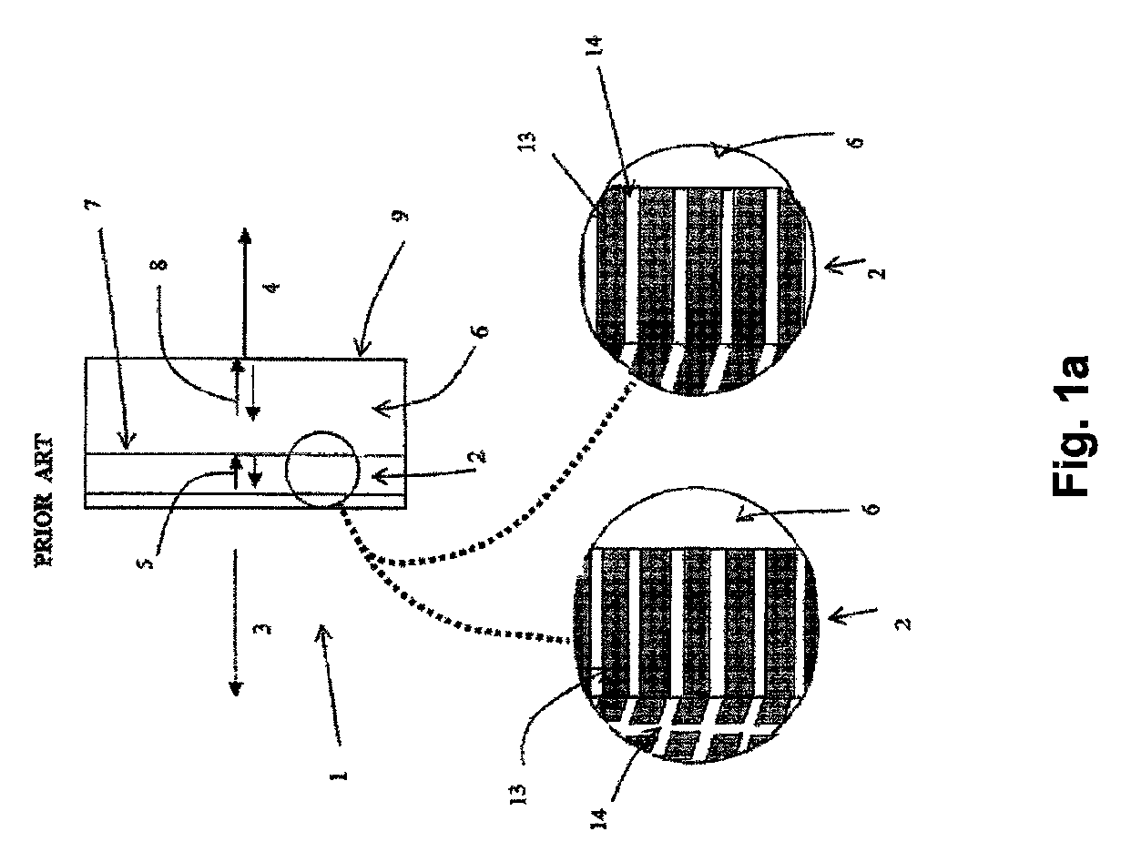
[0026]FIG. 1a shows a structure 1 of a typical ultrasonic transducer operative in thickness vibration mode. Layer 2 represents a vibratory material layer such as a piezoelectric material layer 2, and is typically comprised of (but not limited to) a layer of PZT or single crystal, the thickness of which vibrates in the MegaHertz (MHz) frequency range in response to a stimulus such as an electrical signal applied to the transducer using drive circuitry or an incoming acoustic wave, as understood by one of ordinary skill in the arts. The material of layer 2 is not necessarily uniform but often a composite material of ceramic and polymer is used. An ultrasonic wave is radiated to the front direction 3 and used f...


PUM

PropertyMeasurementUnit
angleaaaaaaaaaa
pressureaaaaaaaaaa
sizeaaaaaaaaaa

Abstract

A multilayer backing absorber for use with an ultrasonic transducer comprises an elemental multilayer having at least one metal layer and at least one adhesive layer, wherein the backing absorber is adapted to be coupled to a vibrating layer of the ultrasonic transducer.

Description

CROSS REFERENCE TO APPLICATIONS[0001]This application claims benefit of and priority to U.S. Provisional Patent Application Ser. No. 61 / 005,584, filed Dec. 6, 2007, which application is incorporated by reference herein in its entirety.FIELD OF THE INVENTION[0002]The present invention generally relates to a multilayer backing absorber for an ultrasonic transducer and more specifically relates to a multilayer backing absorber having an acoustic impedance and absorption adapted according to a desired sensitivity and / or bandwidth.BACKGROUND OF THE INVENTION[0003]Backing absorbers for ultrasonic transducers are typically comprised of metal particles and other binder composites. U.S. Pat. Nos. 3,973,152, 4,090,153, 4,582,680, and 6,814,618 describe such prior art backing absorbers. U.S. Pat. No. 3,973,152 describes a pressure applied to a multilayer metallic foil that performs as an absorber. However, such structures and techniques are deficient in several aspects. For example, ultrasonic...

Claims


Application Information

Patent Timeline
Patent Type & Authority Patents(United States)
IPC IPC(8): H04R17/00H01L41/02
CPCB06B1/06G10K11/002Y10T156/10Y10T428/24132Y10T428/3154
Inventor TODA, MINORUTHOMPSON, MITCHELL L.
Owner MEASUREMENT SPEC
Why Eureka
Try Eureka