Method for determining the closing time of an electromagnetic fuel injector

a fuel injector and electromagnetic technology, applied in the direction of electrical control, switch power arrangement, instruments, etc., can solve the problems of high difficulty in determining the piloting time, extremely costly in reducing dispersion, and inability to determine the piloting time, so as to achieve easy and cost-effective implementation

Active Publication Date: 2013-10-29
MARELLI EURO SPA
View PDF11 Cites 7 Cited by
  • Summary
  • Abstract
  • Description
  • Claims
  • Application Information

AI Technical Summary

Benefits of technology

[0012]It is an object of the present invention to provide a method for determining the closing time of an electromagnetic fuel injector, which is free from the above-described drawbacks and, in particular, is easy and cost-effective to implement.

Problems solved by technology

Consequently, the use of an electromagnetic injector in ballistic zone B is highly problematic, because it is impossible to determine the piloting time T needed to inject a quantity of desired fuel Q with sufficient accuracy.
However, in light of the fact that minor variations to the thickness of the gap have a considerable impact on injection features in ballistic zone B, it is very complex and consequently extremely costly to reduce dispersion of injection features in ballistic zone B by reducing the dispersion of gap thickness.
The matter is further complicated by the aging phenomena of a fuel injector which can result in a creep of injection features over time.

Method used


Image

  • Method for determining the closing time of an electromagnetic fuel injector
  • Method for determining the closing time of an electromagnetic fuel injector
  • Method for determining the closing time of an electromagnetic fuel injector

Examples


Embodiment Construction

)

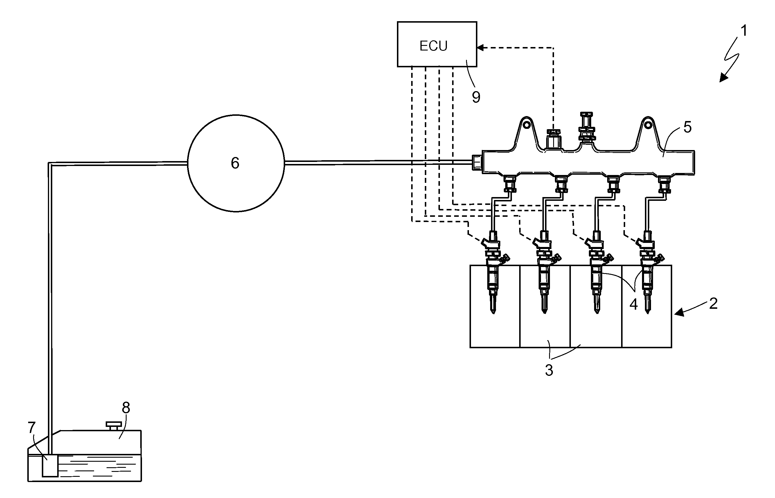
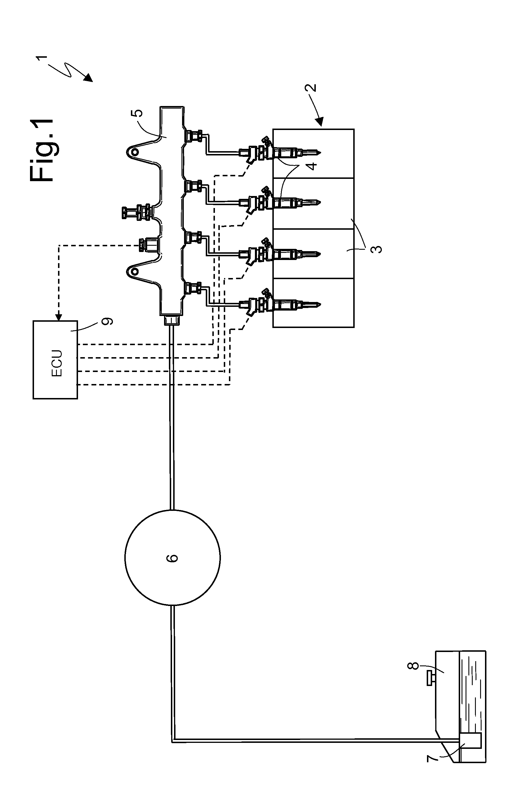
[0022]In FIG. 1, numeral 1 indicates as a whole an injection assembly of the common-rail type system for the direct injection of fuel into an internal combustion engine 2 provided with four cylinders 3. The representative injection system 1 includes four electromagnetic fuel injectors 4, each of which injects fuel directly into a respective cylinder 3 of the engine 2 and receives pressurized fuel from a common rail 5. The injection system 1 comprises a high-pressure pump 6 which feeds fuel to the common rail 5 and is actuated directly by a driving shaft 2 of the engine by means of a mechanical transmission, the actuation frequency of which is directly proportional to the revolution speed of the driving shaft. In turn, the high-pressure pump 6 is fed by a low-pressure pump 7 arranged within the fuel tank 8. Each injector 4 injects a variable quantity of fuel into the corresponding cylinder 3 under the control of an electronic control unit 9.

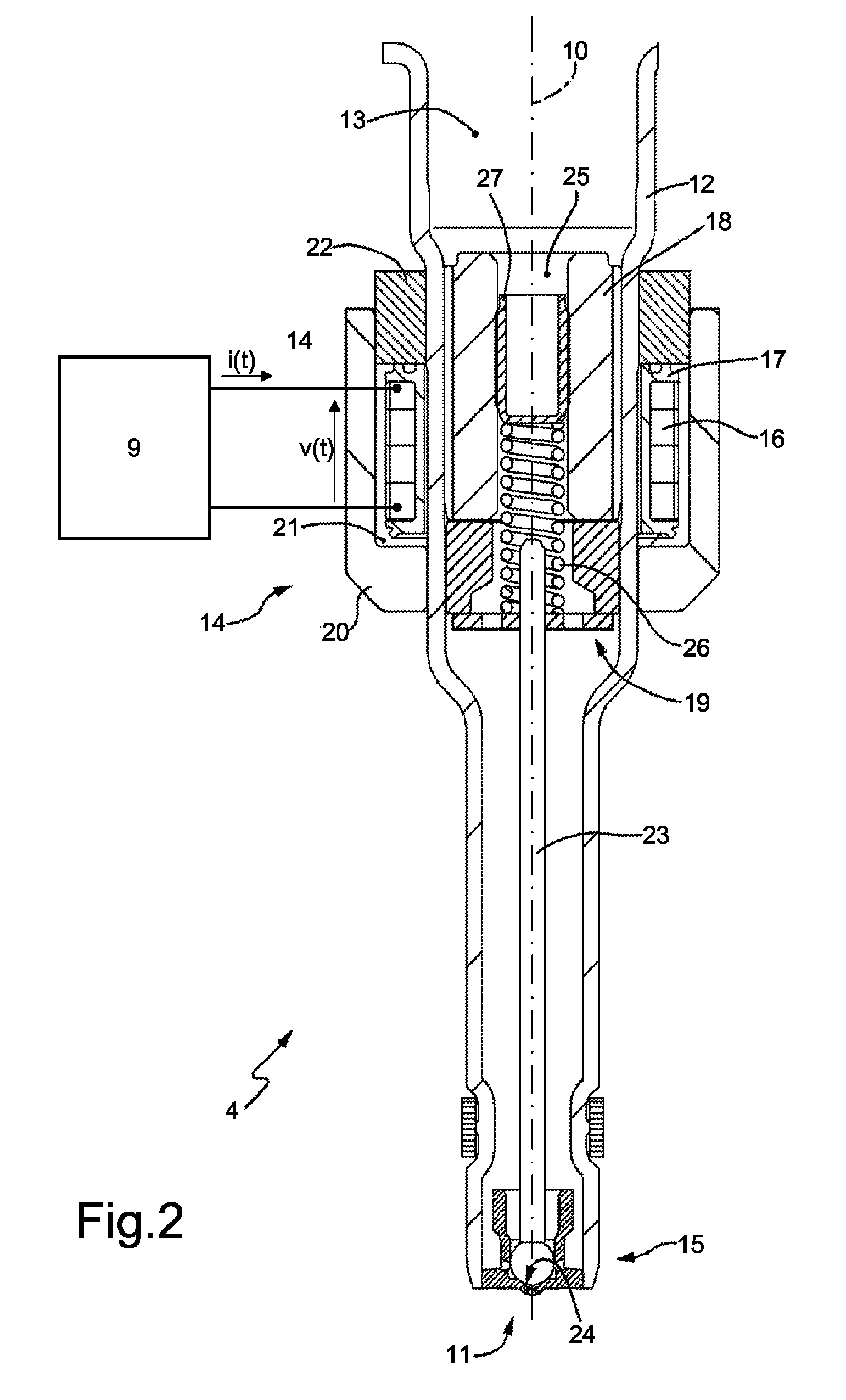
[0023]As shown in FIG. 2, each representat...


PUM


Abstract

A method for determining the closing time of an electromagnetic fuel injector including the steps of applying at a starting time of the injection a positive voltage to the coil of the electromagnetic actuator in order to circulate through the coil an electric current which causes the opening of an injection valve; applying at an ending time of the injection a negative voltage to the coil in order to annul the electric current flowing through the coil; detecting the trend over time of the voltage across the coil after the annulment of the electric current flowing through the coil; identifying a perturbation of the voltage across the coil; and recognizing the closing time of the injector that coincides with the time of the perturbation of the voltage.

Description

BACKGROUND OF THE INVENTION[0001]1. Field of the Invention[0002]The present invention relates to a method for determining the closing time of an electromagnetic fuel injector.[0003]2. Description of the Related Art[0004]An electromagnetic fuel injector of the type described, for example, in patent application EP1619384A2 may include a cylindrical tubular body having a central feeding channel, which performs the fuel conveying function, and ends with an injection nozzle regulated by an injection valve controlled by an electromagnetic actuator. The injection valve is provided with a pin, which is rigidly connected to a mobile keeper of the electromagnetic actuator to be displaced by the action of the electromagnetic actuator between a closed position and an open position of the injection nozzle against the bias of a closing spring. The spring pushes the pin into the closed position. The valve seat is defined by a sealing element, which is disc-shaped, inferiorly and fluid-tightly clos...

Claims


Application Information

Patent Timeline
Patent Type & Authority Patents(United States)
IPC IPC(8): G01R19/00
CPCF02D41/20F02D2041/2055F02M51/061
Inventor SERRA, GABRIELEPAROTTO, MARCOARMENI, SAVERIOSANTAMATO, LUIGITRICARICO, ROMITO
Owner MARELLI EURO SPA
Why Eureka
Try Eureka