
Manufacturing method for a rotation sensor device and rotation sensor device

a manufacturing method and sensor technology, applied in the direction of instruments, devices using electric/magnetic means, acceleration measurement using interia forces, etc., can solve the problems of disadvantageous spring stiffness and/or torsional stiffness, more difficult to situate yaw-rate sensors b>50/b> on a rotatable body, and increase the electrical sensitivity of the rotation sensor device. , increase the capacitance per unit of surface area, increase the effect o

Active Publication Date: 2013-11-05
ROBERT BOSCH GMBH
View PDF21 Cites 0 Cited by
  • Summary
  • Abstract
  • Description
  • Claims
  • Application Information

AI Technical Summary

Benefits of technology

This approach results in a more compact, cost-effective rotation sensor device with improved sensitivity, reduced drive voltage requirements, and minimized cross-sensitivity, enabling better detection of rotational movements with enhanced precision and reduced noise.

Problems solved by technology

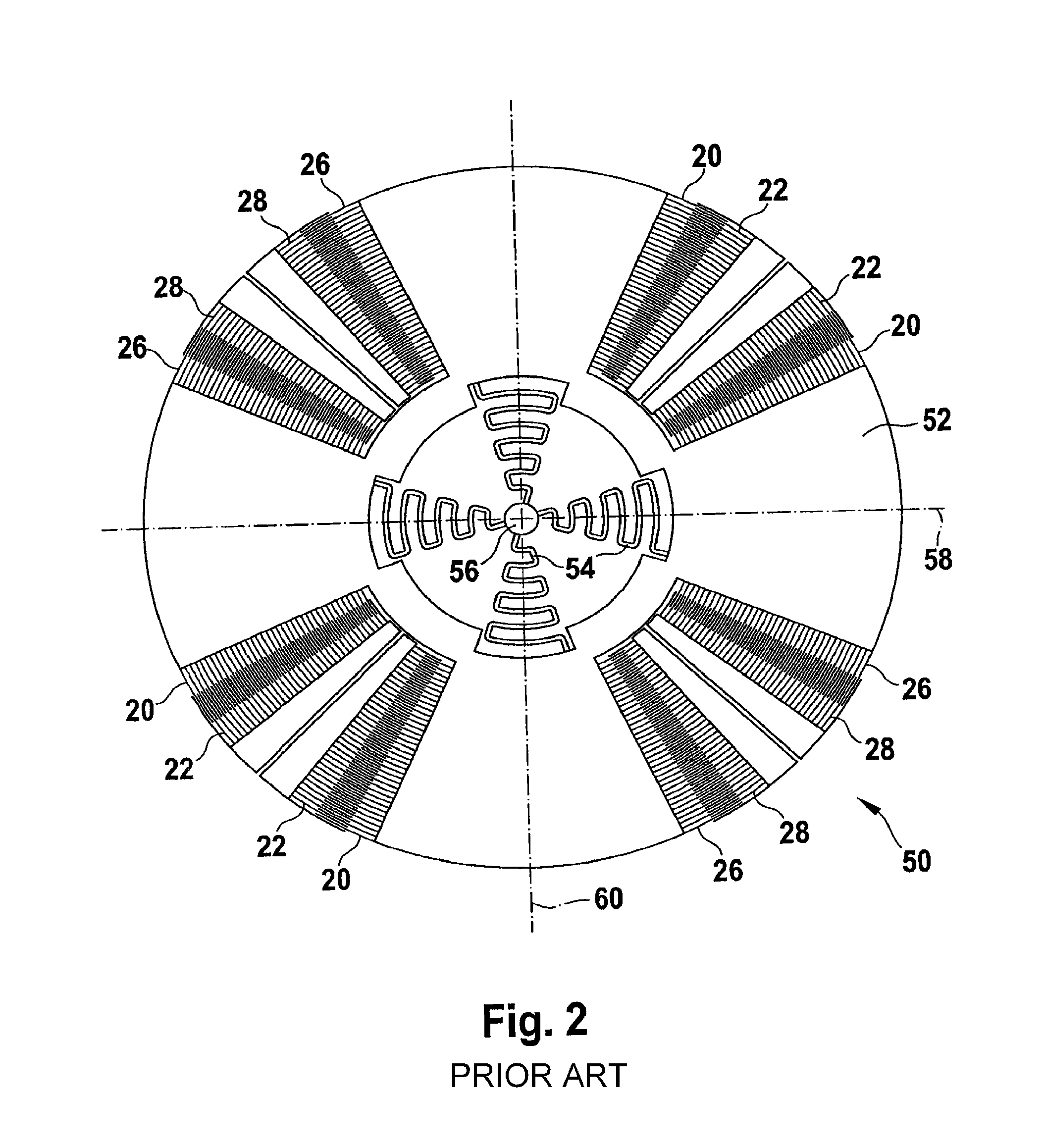
A long minimum length of linear springs increases the total extension of yaw-rate sensor 50 significantly and thus makes it more difficult to situate yaw-rate sensor 50 on a rotatable body.
If meandering springs are used, a precise design layout of the yaw-rate sensor is made significantly more difficult.
Furthermore, the disadvantageous spring stiffness and / or torsional stiffness, which frequently still exists in spite of a relatively great length and / or a meandering shape of spring 54, requires a comparatively high drive voltage of the electrostatic drive having drive electrodes 20 and 22.
However, applying such a high drive voltage places special requirements on the electrostatic drive and thus prevents a cost-effective embodiment of the electronic drive circuit.

Method used


Image

  • Manufacturing method for a rotation sensor device and rotation sensor device
  • Manufacturing method for a rotation sensor device and rotation sensor device
  • Manufacturing method for a rotation sensor device and rotation sensor device

Examples


Embodiment Construction

[0053]FIG. 3 shows a flow chart to illustrate a first specific embodiment of the manufacturing method for a rotation sensor device.

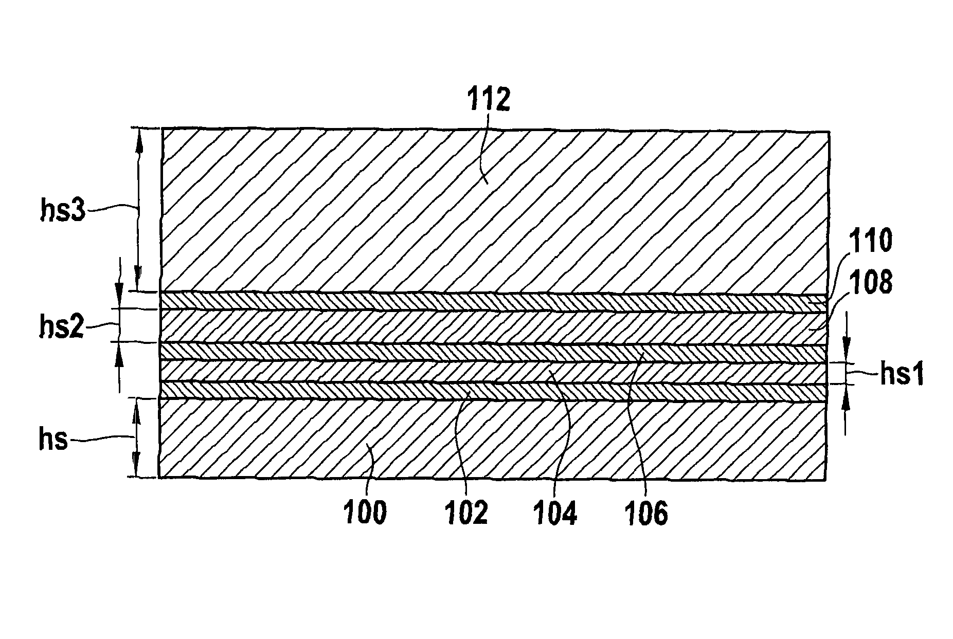
[0054]In a step S1 of the manufacturing method, a layer sequence having at least one layer made of a semiconductor material and / or a metal and a second layer made of a semiconductor material and / or a metal is formed. The first layer and the second layer may have different materials. The two layers may also be formed from the same material. The first layer, for example, has a first layer thickness, which is different from a second layer thickness of the second layer. For example, the first layer thickness is less than the second layer thickness of the second layer. The first layer thickness is significantly less than the second layer thickness. For example, the first layer thickness may be less than the second layer thickness by at least a factor of 5. An insulating layer is formed between the first layer and the second layer, so that a boundary surface o...


PUM

PropertyMeasurementUnit
thicknessaaaaaaaaaa
thicknessaaaaaaaaaa
thicknessaaaaaaaaaa

Abstract

A device and manufacturing method for a rotation sensor device includes a holding device, an oscillating mass, and a spring, via which the oscillating mass is connected to the holding device. The spring is designed so that the oscillating mass can be set into an oscillating movement around an oscillation axis with respect to the holding device with the aid of a drive. The steps include: producing a layer sequence having a first layer made of semiconductor material and / or metal and a second layer made of semiconductor material and / or a metal, a boundary surface of the first layer, at least partially being covered by an insulating layer; structuring the spring out of the first layer; and structuring at least one oscillating mass subunit of the oscillating mass, which can be set into the oscillating movement around the oscillation axis with the aid of the drive, out of the second layer.

Description

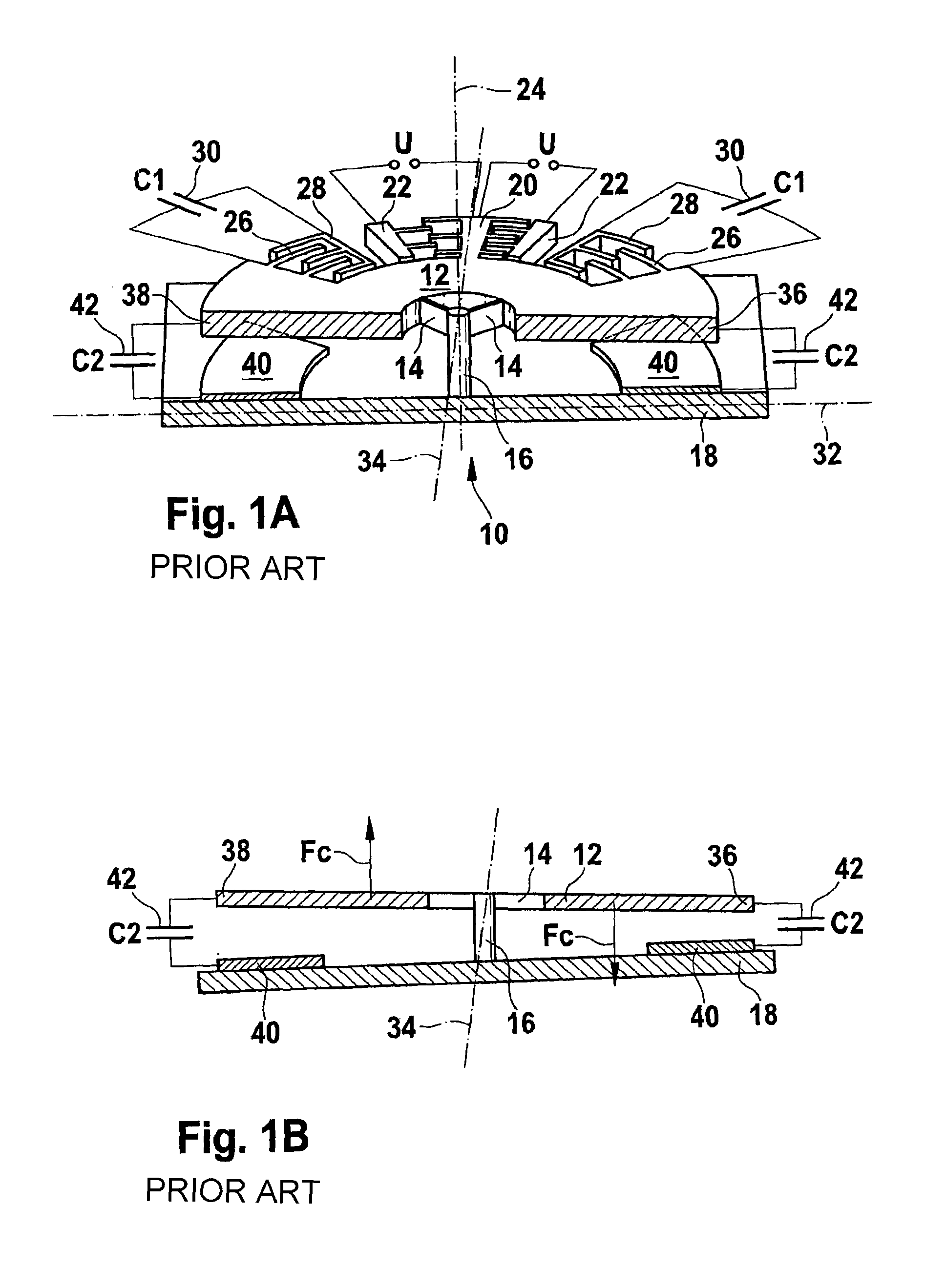
CROSS-REFERENCE TO RELATED APPLICATIONS[0001]The present application claims priority to German Application No. 10 2008 041 757.2, filed in the Federal Republic of Germany on Sep. 2, 2008, which is expressly incorporated herein in its entirety by reference thereto.FIELD OF INVENTION[0002]The present invention relates to a manufacturing method for a rotation sensor device and a corresponding rotation sensor device.BACKGROUND INFORMATION[0003]A micromechanical yaw-rate sensor is frequently used to ascertain information about a rotation behavior of a rotatable body.[0004]FIGS. 1A and 1B show schematic illustrations of a typical micromechanical yaw-rate sensor having a sensitive axis to explain its functionality. The typical yaw-rate sensor is described in German Patent Application No. DE 195 23 895 A1.[0005]Illustrated yaw-rate sensor 10 has a disc-shaped oscillating mass 12, which is connected via multiple springs 14 to a hub 16. Of the total of four springs 14, however, only two are s...

Claims


Application Information

Patent Timeline
Patent Type & Authority Patents(United States)
IPC IPC(8): G01C19/00G01C19/5712
CPCG01C19/5712G01C25/00Y10T29/49124
Inventor CLASSEN, JOHANNES
Owner ROBERT BOSCH GMBH
Learn More