Angular velocity sensor

a technology of angular velocity and sensor, which is applied in the direction of acceleration measurement using interia force, turn-sensitive devices, instruments, etc., can solve the problems of generating vibration components in the y-axis direction, oblique vibration of vibrators, and inability to accurately detect angular velocity, so as to achieve the effect of detecting disconnection

Active Publication Date: 2013-11-05
DENSO CORP +1
View PDF8 Cites 2 Cited by
  • Summary
  • Abstract
  • Description
  • Claims
  • Application Information

AI Technical Summary

Benefits of technology

[0016]At this time, the second-axis vibration restricting part feedback-controls the driving signal supplying part based on the vibration component in the second direction indicated by the second-axis vibration signal so that the vibration of the movable part in the second direction is restricted. That is, the second-axis vibration restricting part controls the driving signal supplying part so that an electrostatic force for restricting the vibration of the movable part in the second direction is generated between the movable electrode to which the carrier signal is applied and the driving electrode. By such a servo control, oblique vibration of the movable part caused by machining error or the like is reduced, and the movable part can be simply vibrated in the first direction.
[0018]In this way, disconnection of the driving signal transmission line can be detected. Also, the determination of disconnection is made based on the voltage outputted from the C / V converter. Therefore, it is possible to detect the disconnection, even if the movable part is in an ideal condition without causing oblique vibration.

Problems solved by technology

In an angular velocity sensor, although a vibrator is vibrated in the X-axis direction, a vibration component in the Y-axis direction will be generated due to machining error of the vibrator and the like.
That is, the vibrator may vibrate obliquely due to the machining error.
If the connecting portion has disconnection, the angular velocity will not be accurately detected, as well as a malfunction will occur.
Therefore, because the driving signal for the servo control does not pass through the connecting portion, the disconnection of the connecting portion cannot be detected.

Method used


Image

  • Angular velocity sensor
  • Angular velocity sensor
  • Angular velocity sensor

Examples


first embodiment

[0024](First Embodiment)

[0025]A first embodiment of the present invention will be described hereinafter with reference to FIGS. 1 through 3.

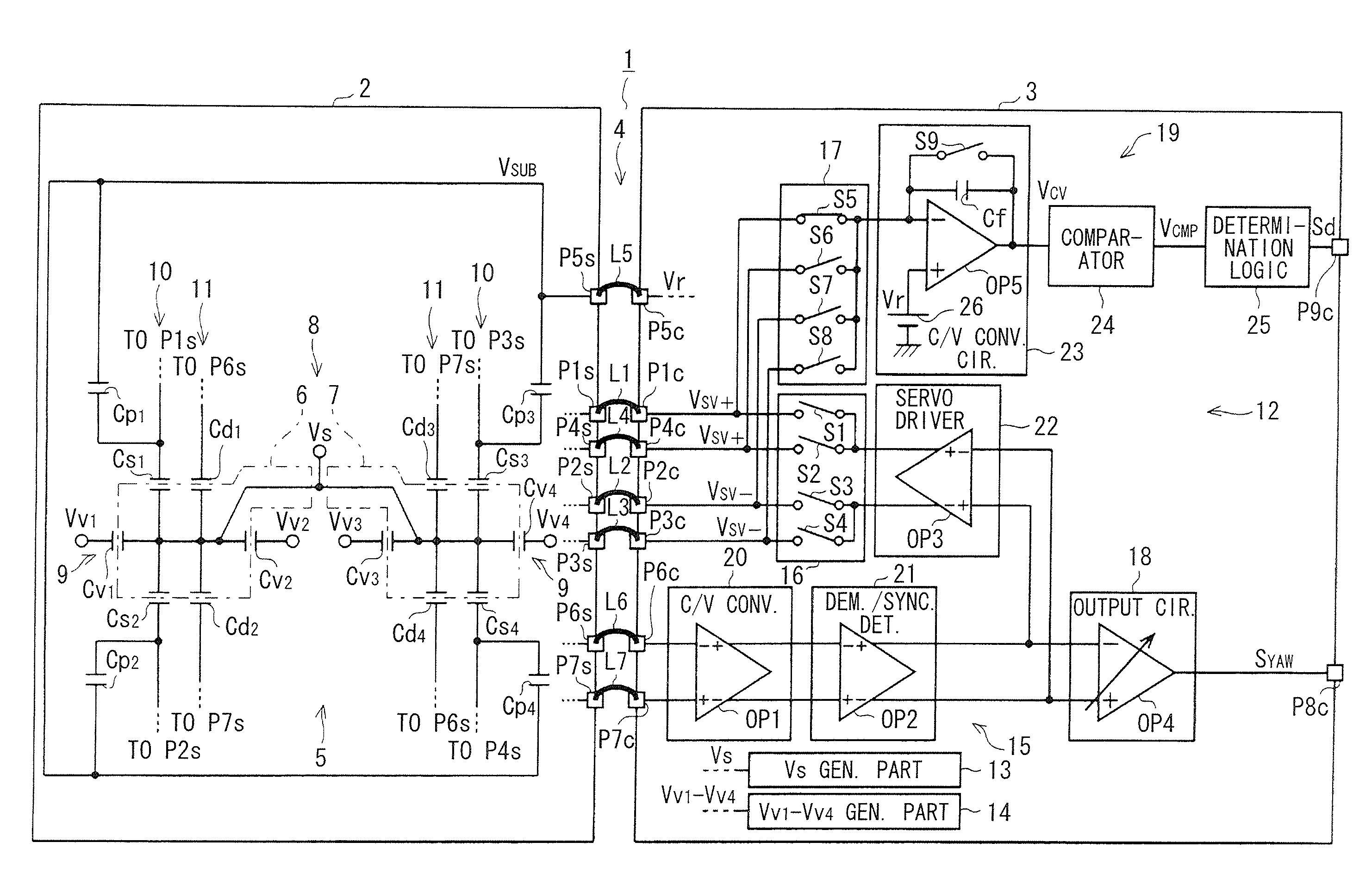
[0026]Referring to FIG. 1, an angular velocity sensor 1 is, for example, employed as a yaw rate sensor. The angular velocity sensor 1 generally includes a sensor chip 2 as a first semiconductor chip, a circuit chip 3 as a second semiconductor chip, and a connecting part 4 that electrically connects the sensor chip 2 and the circuit chip 3.

[0027]The connecting part 4 includes multiple connection lines. The sensor chip 2 and the circuit chip 3 are connected through the multiple connection lines by a flip-chip bonding technique. In FIG. 1, only seven connection lines, such as lines L1 through L7, are exemplarily illustrated. It is to be noted that the connection lines mean bonding portions or connecting portions between bumps formed on the sensor chip 2 and the circuit chip 3. The sensor chip 2 is provided with terminals P1s through P7s. The circui...

second embodiment

[0088](Second Embodiment)

[0089]A second embodiment of the present invention will be described hereinafter with reference to FIG. 4.

[0090]FIG. 4 is a schematic diagram of an angular velocity sensor 31 according to the second embodiment. In the second embodiment, components similar to those of the first embodiment are designated with like reference numbers, and a description thereof will not be repeated. The angular velocity sensor 31 is different from the angular velocity sensor 1 shown in FIG. 1 because the circuit chip 3 additionally has an inspection circuit 32.

[0091]The inspection circuit 32 has a capacitor C31 and switches S31, S32. One of terminals of the capacitor C31 is connected to an inverting input terminal of the operation amplifier OP5 of the C / V converter circuit 23. The other of the terminals of the capacitor C31 is connected to one of terminals of the switch S31 and one of terminals of the switch S32. The other of the terminals of the switch S31 is connected to a term...


PUM


Abstract

An angular velocity sensor includes a sensor unit, a detection unit and a connecting part electrically connecting the sensor unit and the detection unit. The detection unit drives the sensor unit and detects an angular velocity acting on the sensor unit. The detection unit supplies a carrier signal to a movable electrode of a capacitor of the sensor unit and supplies a driving signal to a fixed electrode of the capacitor via the connecting part for performing a servo control. A C / V converter circuit of the detection unit receives capacitance generated at the capacitor through a driving signal transmission line of the connecting part in a state where supply of the driving signal is stopped, and converts the capacitance into a voltage. A determination part of the detection unit determines whether the driving signal transmission line has disconnection or not based on the voltage outputted from the C / V converter circuit.

Description

CROSS REFERENCE TO RELATED APPLICATION[0001]This application is based on Japanese Patent Application No. 2010-118305 filed on May 24, 2010, the disclosure of which is incorporated herein by reference.FIELD OF THE INVENTION[0002]The present invention relates to an angular velocity sensor. More particularly, the present invention relates to a vibration-type angular velocity sensor that has a movable part movable in a first direction and a second direction perpendicular to the first direction, and detects an angular velocity applied around an axis perpendicular to the first direction and the second direction based on vibration of the movable part in the second direction in a state where the movable part is vibrating in the first direction.BACKGROUND OF THE INVENTION[0003]In general, a vibration-type angular velocity sensor has a movable part, that is, a vibrator that is movable in a direction along an X-axis (hereinafter, X-axis direction) and a direction along a Y-axis (hereinafter, t...

Claims


Application Information

Patent Timeline
Patent Type & Authority Patents(United States)
IPC IPC(8): G01C19/56G01C19/00G01C19/5726G01C19/574
CPCG01C19/5776
Inventor ITAKURA, TOSHIKAZU
Owner DENSO CORP
Why Eureka
Try Eureka