Multipurpose seasonal safety support fence

Active Publication Date: 2013-11-05
GRAND SLAM SAFETY
View PDF28 Cites 19 Cited by
  • Summary
  • Abstract
  • Description
  • Claims
  • Application Information

AI Technical Summary

Benefits of technology

The present invention is a fence that aims to protect players from injury when running into it. It is constructed of vinyl-coated mesh and steel posts, which are anchored in the ground to maintain its integrity, both during play and high winds. The fence provides a gentle repelling effect, giving the player a comfortable experience while playing the game. The fence is not a permanent structure and can be easily moved around for other activities. Overall, the invention provides an outfield fence that bounds the field realistically while minimizing the possibility of impact injury.

Problems solved by technology

Injury to the player is likely where the fence is made of rigid materials.
Misjudgment leads to either unnecessary reluctance of the player to field a ball or to injury.
These problems are more serious for younger, inexperienced players, such as Little League, junior high school, and high school players than for collegiate and professional players.
The weight of the fence, however, makes these materials unsuitable.
In addition to allowing the fence material to sag, they lack the resilience to restore the fence to its original configuration after it deflects from impact.
This situation arises, not from financial limitations (costs of erecting and maintaining fences) but from safety considerations: preventing injury to players.
Moving the outfield fence closer to home plate and thus bringing it into play (thereby improving “playability”) is simply too dangerous if the fence is a solid structure, such as plywood / post or chain-link.
Examples from the prior art address safety from both aspects, “playability” and “continuation of play,” without achieving a satisfactory solution.
This fence cannot contain the impact at full force of a player running at full speed.
The “mesh net” boundary fence cannot be adapted to protect players on a baseball or softball field, as the mesh is anchored and is secured directly to the solid support posts.
Thus the fence of Leonard et al. presents a significant risk of injury to a player who runs into it.
. . deflect under the weight of impact.” Though this design is not a solid structure and therefore poses no threat of impact injury, it cannot prevent the player from literally toppling over the fence as it collapses.
Moreover, the height of the fence of Schmanski & Landis makes it possible for a player to jump high enough, while reaching for a ball, to go over the fence backwards, thereby risking a head injury.
The pull of the player's legs against the fence may not be sufficient to cause the fence to collapse completely yet be strong enough to cause players to topple onto their heads.
U.S. Pat. No. 5,029,819 (Jul. 9, 1991) to Kane for “Handling and Supporting Flexible Material of a Fence” also discloses mesh material directly attached to rigid support posts, thereby creating a threat of injury if applied to an outfield fence for a baseball or softball field.
Brower's fence posts “either bend or break to avoid injury to the player.” A broken post is itself a risk to the player who falls on it.
Like the fence of Schmanski & Landis, the height of Brower's fence also poses a hazard if players end up on their heads.
U.S. Pat. No. 6,176,471 (Jan. 23, 2001) to Naegele and Loven for a “Fabric Fence System” also discloses mesh affixed directly to a rigid support structure that includes both vertical and cross members, thereby creating a threat of injury to players.
Penning discloses a framed structure of insufficient height and flexibility.
Thus Penning's fence cannot provide both mitigation of the risk of injury and continuation of play.
The verticality of a fall by the player increases the chance of injury because a structure framed or supported by posts offers increased resistance along its vertical plane.
Thus a player near the fence who jumps vertically to catch a ball may, because of the fence's short height, fall vertically, thereby challenging the fence's vertical strength.
Posts or other framing may cause serious injury to the player by offering significant resistance to a downward force exerted by a falling player.
In addition, none of the structures of the prior art as assembled respond to the effects of high winds.

Method used


Image

  • Multipurpose seasonal safety support fence
  • Multipurpose seasonal safety support fence
  • Multipurpose seasonal safety support fence

Examples


Embodiment Construction

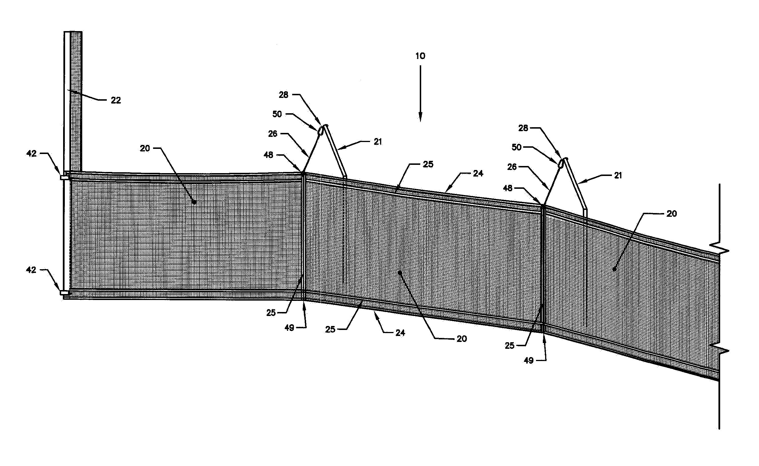
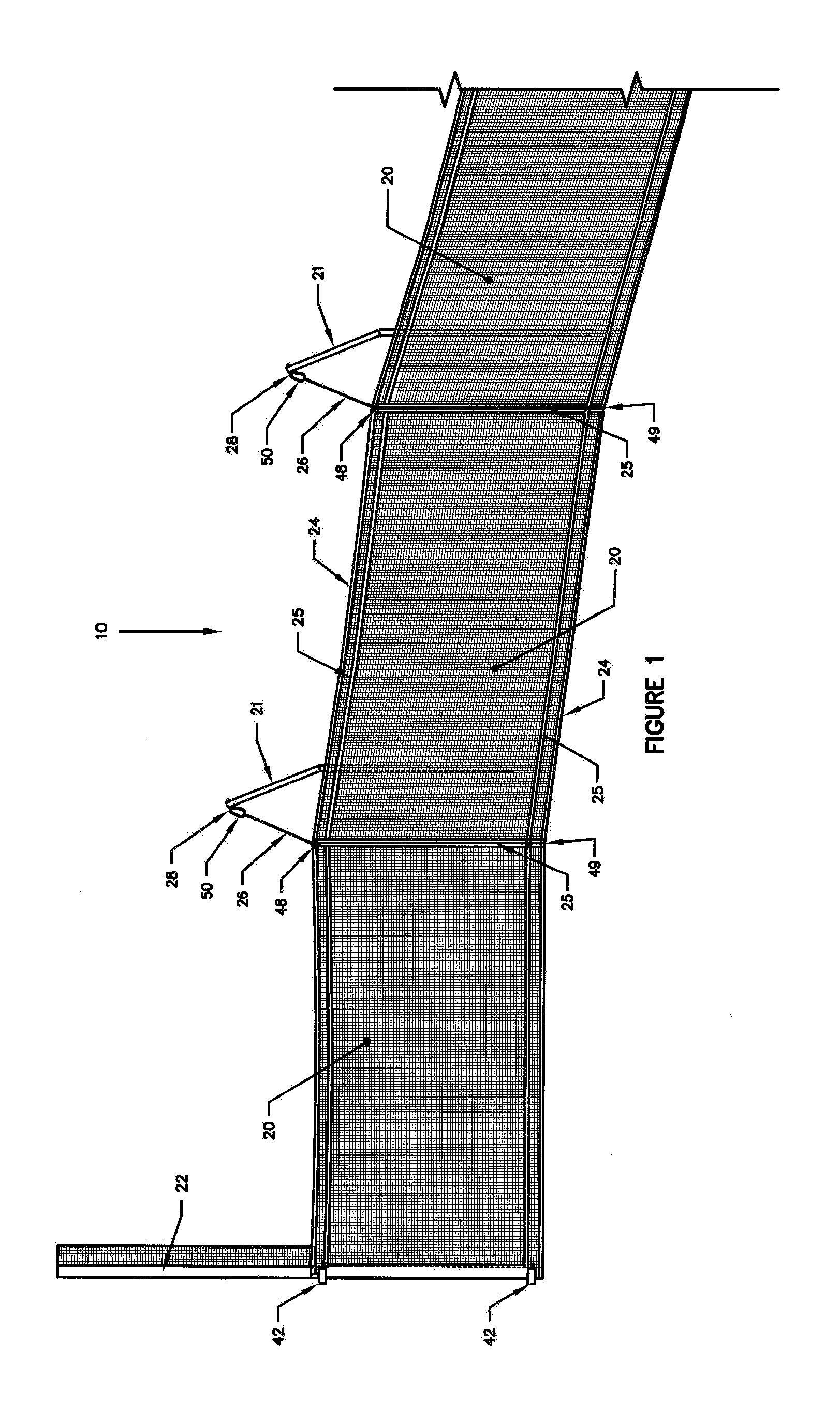
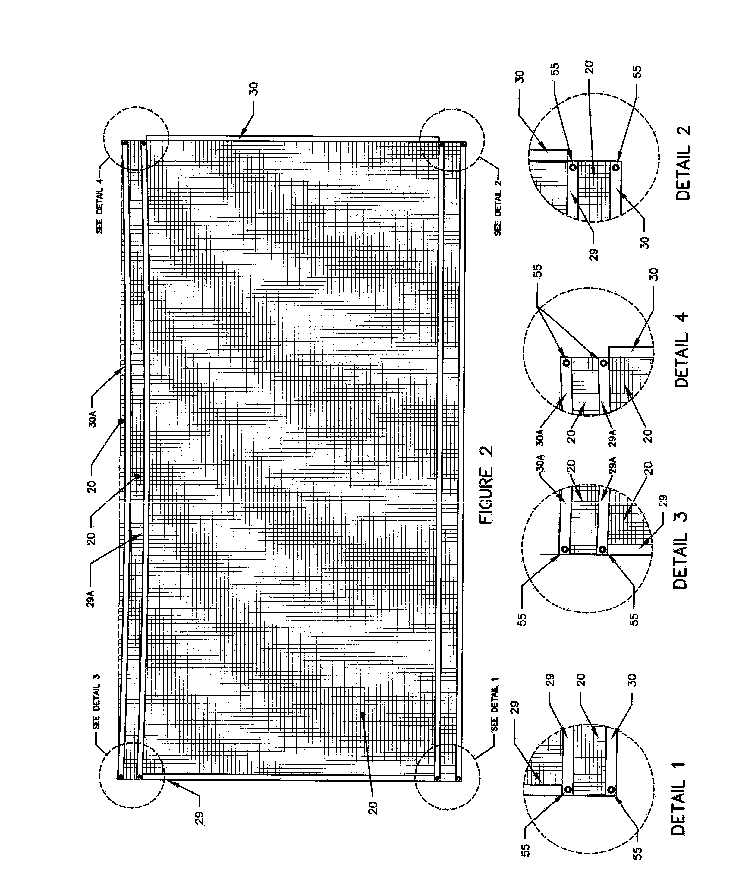
[0037]Referring to FIG. 1, a multipurpose seasonal sport safety fence 10 can be an outfield fence for baseball and softball fields of all sizes. The fence structure comprises a plurality of mesh panels 20 of a height determined by the size and age of the players and a length chosen so that the number of panels bounds the field from a left-hand foul pole 22 to a right-hand foul pole 22 (not shown). Panels 20 are suspended by a tie cable / PVC assembly 24 secured to a diagonal connector cable 26 and a snap link 50. Snap link 50 is attached to an eyebolt 28 mounted to the top of a steel support post 21 mounted behind each mesh panel 20. A plurality of steel support posts 21 are laid out in an arc from left-hand foul pole 22 to right-hand foul pole 22 (not shown). The bottom of fence 10 is secured by a bottom anchor and bottom tie cable assembly 49. Seams of mesh panels 20 are secured by hook and loop rope assemblies 25 made up of a wide hook rope 29, a narrow hook rope 29A, a wide loop r...


PUM


Abstract

A fence that bounds the outfield of a game played with bat and ball comprises a plurality of mesh panels suspended from a plurality of support posts, with foul posts at either end. The fence can be readily assembled and disassembled. The support posts' anchors can be covered when the fence is disassembled, so that the field is usable for other sports. The function of the fence is twofold: (1) to minimize injury to a player who runs into the fence and (2) to confine such a player within the field of play should the player impact the fence.

Description

BACKGROUND OF THE INVENTION[0001]This invention pertains to a fence useful for a sports field where an athlete can collide with the fence. More specifically, this invention offers a fence that provides containment to a player who runs into the fence. In the present invention, the player comes into contact with a mesh that repels him back onto the field of play with minimum risk of injury. After repelling a player, the safety fence returns to its prior position, thereby maintaining play without disruption.[0002]In many sports, fence-like structures define the perimeter of play. For example, a baseball diamond includes an outfield bounded by a fence (or wall). If a batter hits a baseball beyond the fence, he scores a home run. Accordingly, a baseball player in the outfield may jump up to catch a ball likely to go over the fence.[0003]In these circumstances, the player may collide with the fence, because the player runs toward the fence when he realizes that the ball is sufficiently hi...

Claims


Application Information

Patent Timeline
IPC IPC(8): A01G17/06
CPCA63B71/0054A63B71/022E04H17/16A63B71/028A63B71/023E04H17/161
Inventor LYNDAKER, BOBCHAMBERLAIN, BOBMOORE, DAVELEHMAN, MICKEY
Owner GRAND SLAM SAFETY
Why Eureka
Try Eureka