Improvements for rapid prototyping apparatus

a technology of rapid prototyping and prototyping equipment, which is applied in the field of rapid prototyping apparatus to achieve the effect of facilitating the transmission of ligh

Active Publication Date: 2013-11-05
3D SYST INC
View PDF13 Cites 1 Cited by
  • Summary
  • Abstract
  • Description
  • Claims
  • Application Information

AI Technical Summary

Benefits of technology

[0006]The invention relates to an exposure system for a stereolithography apparatus comprising at least one light emitting diode emitting light with a wavelength between 200 and 10000 nm, at least one spatial light modulator, with a plurality of individually controllable light modulators, input optics optically coupled to said at least one spatial light modulator, output optics optically coupled to said at least one spatial light modulator, at least one control unit, wherein said input optics and output optics facilitates transmission of light emitted from said at least one light emitting diode via said individually controllable light modulators of said spatial light modulator to an illumination area, wherein said spatial light modulator enables an establishment of a pattern of the light from said input optics, according to control signals from said control unit, wherein said output optics enable focusing of the pattern of light from said at least one spatial light modulator onto an illumination spot, and wherein said exposure system is capable to align light emitted from said light emitting diode at an angle above 45 degrees with respect to the optical axis of the light emitting diode, so as to direct such light in a direction parallel with respect to the optical axis.

Problems solved by technology

Implementing light emitting diodes as light source leads to different problems, which are dealt with in this application.

Method used


Image

  • Improvements for rapid prototyping apparatus
  • Improvements for rapid prototyping apparatus
  • Improvements for rapid prototyping apparatus

Examples


Embodiment Construction

[0158]In using an apparatus according to the present invention for the manufacture of three-dimensional objects a light-sensitive material LSM is used as the material forming the object. A person skilled in the art will know of various types of light-sensitive material suitable for this purpose.

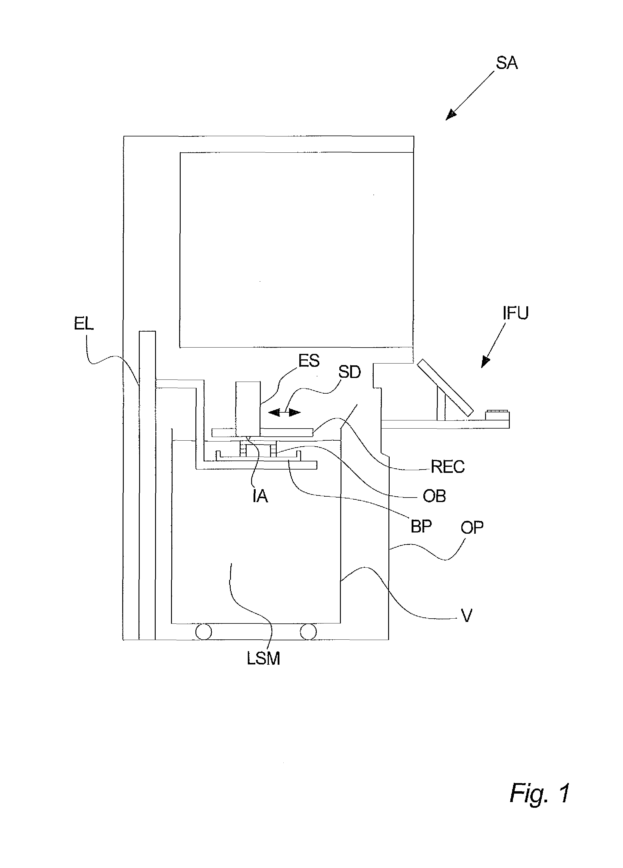
[0159]FIG. 1 illustrates a simplified cross-sectional view of a stereolithography apparatus SA for building three-dimensional objects OB according to one aspect of the present invention. The three-dimensional objects OB are built layer-wise through the curing of light-sensitive material LSM when exposed to light from the exposure system ES.

[0160]The stereolithography apparatus SA comprises a building plate BP on which one or more three-dimensional objects OB are built. The building plate BP is moved vertically into a vat V comprising light-sensitive material LSM by means of an elevator EL. A recoater REC is according to an aspect of the invention scanned across the new layer of light-sensitiv...


PUM

PropertyMeasurementUnit
wavelengthaaaaaaaaaa

Abstract

A stereolithography apparatus and an exposure system for a stereolithography apparatus, wherein light emitting diodes are used as light sources. The invention relates to aligning light from the light emitting diode and to the exchange and control of the light emitting diodes.

Description

CROSS REFERENCE TO RELATED APPLICATIONS[0001]This application is the National Phase of International Application PCT / EP2009 / 063158 filed Oct. 9, 2009 which designated the U.S. and which claims priority to patent applications (EP) 08018226.4 filed Oct. 17, 2008 and PCT / EP2008 / 066644 filed Dec. 2, 2008. The noted applications are incorporated herein by reference.CROSS-REFERENCE TO RELATED APPLICATIONS[0002]1. Field of the Invention[0003]The invention relates to improvements relating to a rapid prototyping apparatus for the manufacturing of three-dimensional objects by additive treatment of cross-sections.[0004]2. Background of the Invention[0005]Apparatuses for use in stereolithography have been developed over the recent years. They now include both UV-light bulbs and light emitting diodes as light sources. Implementing light emitting diodes as light source leads to different problems, which are dealt with in this application.SUMMARY OF THE INVENTION[0006]The invention relates to an e...

Claims


Application Information

Patent Timeline
Patent Type & Authority Patents(United States)
IPC IPC(8): B29C35/08
CPCB29C67/007B29C64/129B33Y30/00B29C67/00B29C35/08
Inventor HANGAARD, OLELARSEN, NIELS HOLMPOUGEOISE, EMILIEGRELIN, JEROME
Owner 3D SYST INC
Why Eureka
Try Eureka