High efficiency electroluminescent devices and methods for producing the same

a high-efficiency, electroluminescent technology, applied in the direction of solid-state devices, semiconductor devices, thermoelectric devices, etc., can solve the problems of low work function metals such as barium or calcium, use of low work function metals, and many drawbacks, and achieve high-efficiency and bright display

Inactive Publication Date: 2013-11-05
SRI INTERNATIONAL
View PDF48 Cites 28 Cited by
  • Summary
  • Abstract
  • Description
  • Claims
  • Application Information

AI Technical Summary

Benefits of technology

[0008]An advantage of an electroluminescent device of the present disclosure is that, in certain embodiments, it includes an air-stable, low work function material, which material may be used as a cathode and / or electron injection layer. Additionally, an advantage of the present disclosure is that it provides methods for producing such devices that overcome the inherent limitations of prior fabrication processes, such as high vacuum deposition, and provides for a high-efficiency and bright display when employed in an electroluminescent display device.

Problems solved by technology

Using low work function metals, such as barium or calcium, as a cathode and / or electron-injection layer in electroluminescent devices, however, suffers from several drawbacks.
For instance, one drawback is that low work function metals are typically very chemically reactive, unstable in air, and rapidly absorb moisture from the ambient environment thereby producing hydrogen gas and the corresponding metal hydroxide.
This reaction results in a loss of the ability of the metal cathode and / or electron-injection layer to inject electrons into the electroluminescent material as the metal is oxidized, and consequently results in a loss of function of the electroluminescent device in which the low work function metal cathode / electron-injection layer is employed.
Accordingly, in order for the device to have a reasonably long lifetime, these devices are traditionally fabricated and encapsulated in an inert, gas environment, which increases the complexity and expense of fabrication.
An additional drawback is that the deposition process by which the metal is deposited on a suitable substrate, so as to produce a low work function cathode layer and / or electron-injection layer, typically involves a high vacuum evaporation process.
A high vacuum evaporation process is disadvantageous because the metal to be deposited must first be evaporated and then deposited in a vacuum, which process is complex, time consuming, and expensive.

Method used


Image

  • High efficiency electroluminescent devices and methods for producing the same
  • High efficiency electroluminescent devices and methods for producing the same
  • High efficiency electroluminescent devices and methods for producing the same

Examples


Embodiment Construction

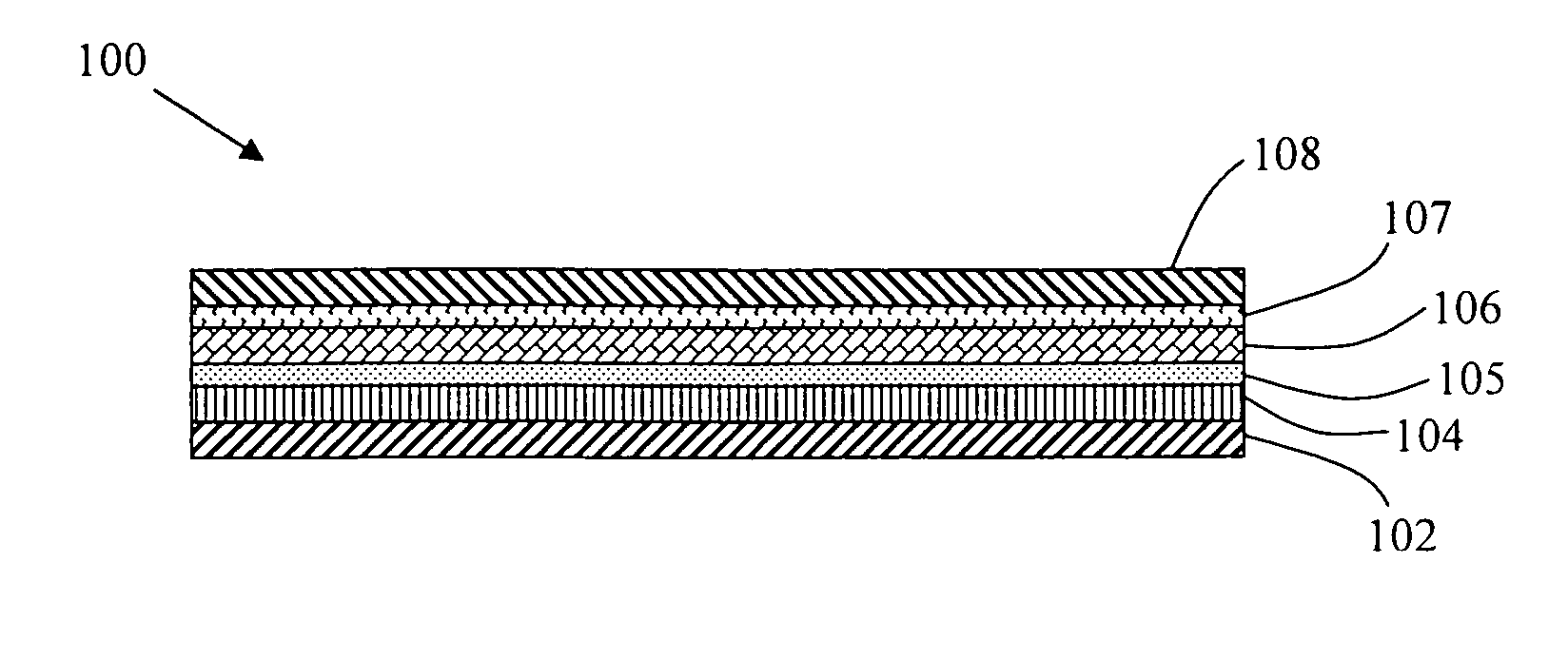
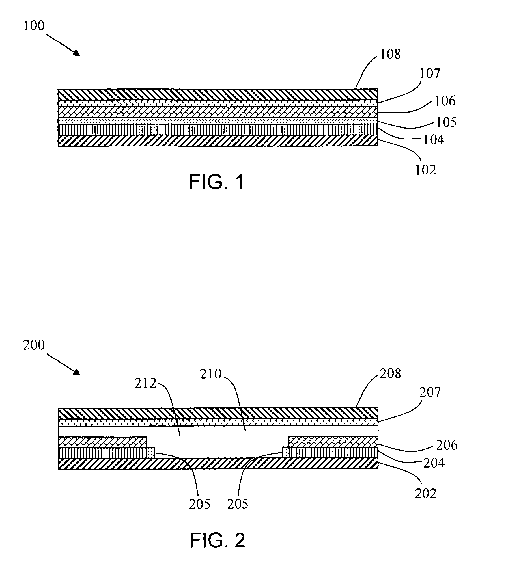
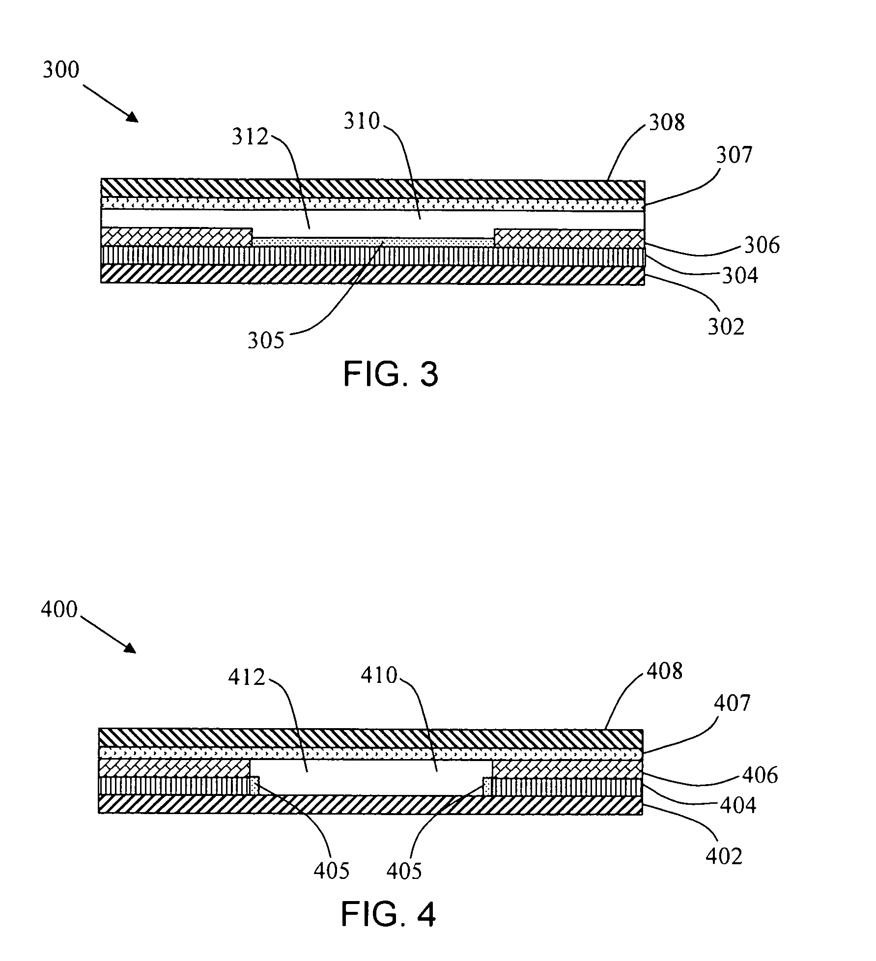
[0051]Aspects of the disclosure include electroluminescent devices and methods for making the same. In certain embodiments, the devices include a substrate, a hole-injection electrode layer, an electroluminescent layer, and an electron-injection electrode layer. In certain embodiments, the devices further include an anode and cathode layers. In certain embodiments, the devices may include a cavity and / or a dielectric layer. In certain embodiments, the electroluminescent devices contain an efficient electron-injection electrode layer, such as a layer that includes an air-stable, low work function material, which layer is capable of achieving efficient electron injection with reduced current leakage.

[0052]For instance, in certain embodiments, the devices may contain an efficient electron injection layer that includes a composition comprising a polymer and a metal diketonate. In certain embodiments, a suitable polymer containing at least one polar component may be one or more of polyet...


PUM

PropertyMeasurementUnit
thicknessaaaaaaaaaa
thicknessaaaaaaaaaa
thicknessaaaaaaaaaa

Abstract

Aspects of the disclosure include electroluminescent devices and methods for making the same. The devices include a substrate, a hole-injection electrode layer, an electroluminescent layer, and an electron-injection electrode layer, such as a layer that includes an air-stable, low work function material, which layer is capable of achieving efficient electron injection with reduced current leakage. In certain embodiments, the devices may contain an efficient electron injection layer that includes a composition comprising a polymer, e.g., a polymer that contains polar components (such as a polar functional group), and a metal diketonate. In certain embodiments, the devices may contain an electron injection layer that includes polyethylene glycol dimethyl ether and barium or calcium acetylacetonate. Methods of manufacturing such devices, for instance, employing a solution processing step for the deposition of an electron injection layer, as well as the use of the produced device(s) in electroluminescent displays is also provided herein.

Description

BACKGROUND OF THE DISCLOSURE[0001]Electroluminescent devices for use in electroluminescent displays, such as flat panel displays, are well known in the industry and are set forth in U.S. Pat. No. 5,247,190 to Friend et al.; U.S. Pat. No. 5,682,043 to Pei et al.; U.S. Pat. No. 5,723,873 to Yang; as well as Baigent et al. (1994), “Conjugated Polymer Light-Emitting Diodes on Silicon Substrates,” Appl. Phys. Letter, 65(21):2636-38. Electroluminescent devices, therefore, may be fabricated upon a suitable substrate in a multilayer thin-film configuration, such as, for example, wherein a layer of electroluminescent material is positioned between an electron-injection and a hole-injection electrode layer in a “sandwich” configuration. When a voltage gradient is applied across the electrode layers, holes and electrons are injected into the electroluminescent material from the hole-injection and electron-injection electrode layers, respectively, which results in the emission of light through ...

Claims


Application Information

Patent Timeline
Patent Type & Authority Patents(United States)
IPC IPC(8): H01L21/00
CPCH01L51/5012H01L51/5092H01L51/004H01L51/0077H10K85/141H10K85/30H10K50/171H10K50/11
Inventor SHI, YIJIAN
Owner SRI INTERNATIONAL
Why Eureka
Try Eureka