Headlamp LED lighting apparatus and vehicle headlamp lighting system

a headlamp and led lighting technology, applied in the direction of electric lighting sources, electroluminescent light sources, transportation and packaging, etc., can solve the problems of complicating configuration and inability to accurately detect failures, and achieve the effect of reducing influence and ensuring reliability

Inactive Publication Date: 2013-11-05
MITSUBISHI ELECTRIC CORP
View PDF6 Cites 9 Cited by
  • Summary
  • Abstract
  • Description
  • Claims
  • Application Information

AI Technical Summary

Benefits of technology

[0012]With such a configuration, it has an advantage of being able to positively detect the variation in the output voltage, which changes sharply owing to the LED failure, from the output voltage that varies every moment with a simple arrangement without requiring wiring for monitoring the forward voltage of an LED. For example, using for the decision the average of the output voltage obtained by a number of times of samplings makes it possible to reduce influence due to the variation in the LED lighting voltage because of the temperature change, thereby being able to make a failure detection with higher reliability.

Problems solved by technology

Thus, since the amount of light emission of the individual LEDs is small, it can easily occur that even if a part of the LEDs of the headlamps has stopped, a driver does not become aware of that.
As the foregoing documents offer as a problem, if the plurality of LEDs connected in series have variation in the forward voltage of the individual LEDs, even if the forward voltage of a single LED in the block of the series connection becomes zero volt because of a short circuit failure or becomes a Zener voltage of its parallel Zener diode because of an open failure, they are hidden under a variation tolerance of the output voltage of the LED lighting apparatus, and a decision of the failure cannot be made from only the output voltage.
Although measuring the forward voltage of each of the plurality of LEDs constituting the LED block makes it possible to locate the failure, this is not reasonable because the configuration becomes complicated and a large number of measuring operations are very troublesome.
Accordingly, the Patent Document 2, which employs only instantaneous voltage changes, has a problem of being unable to detect a failure accurately.
In addition, the Patent Document 1, which monitors the forward voltage of a single LED to correct the changes in the forward voltages of the LEDs, has a problem of requiring new wiring for measuring the voltage and thus complicating the configuration.

Method used


Image

  • Headlamp LED lighting apparatus and vehicle headlamp lighting system
  • Headlamp LED lighting apparatus and vehicle headlamp lighting system
  • Headlamp LED lighting apparatus and vehicle headlamp lighting system

Examples


embodiment 1

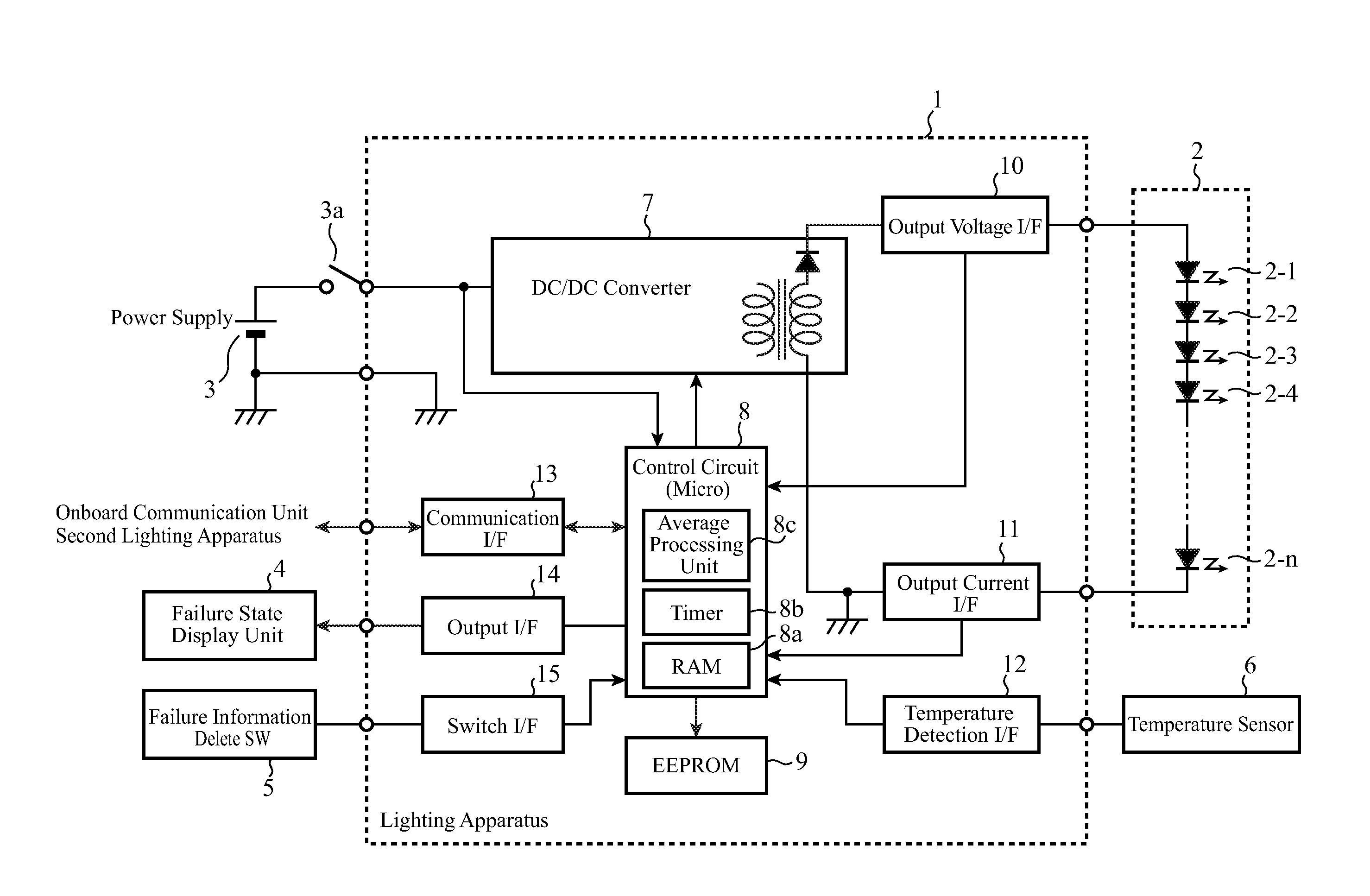
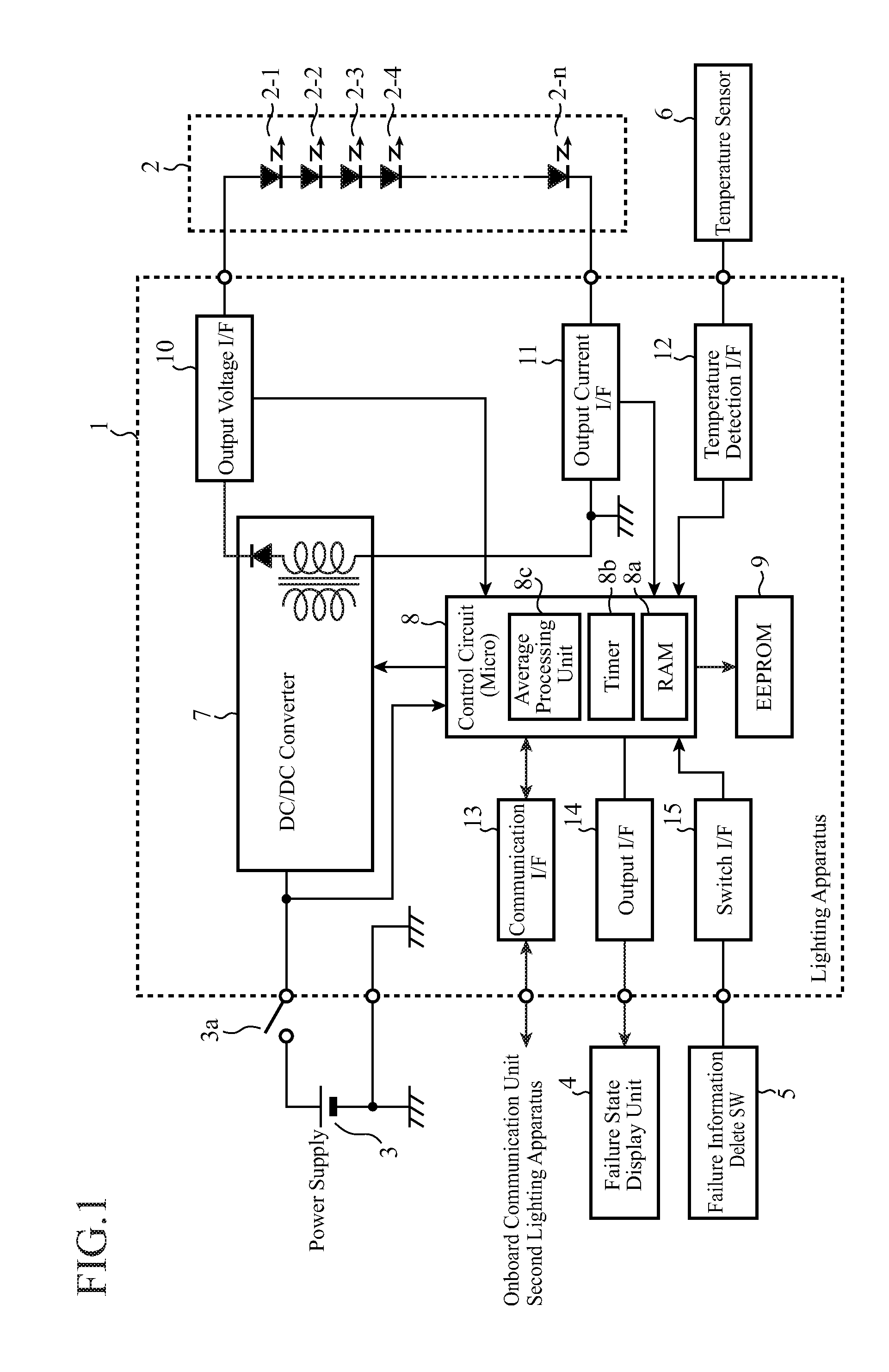
[0019]FIG. 1 is a block diagram showing a configuration of a headlamp LED lighting apparatus of an embodiment 1 in accordance with the present invention. In FIG. 1, the headlamp LED lighting apparatus 1 of the embodiment 1 has as its peripheral components an LED block 2, a power supply 3, a power supply switch 3a, a failure state display unit 4, a failure information delete switch (SW) 5 and a temperature sensor 6; and comprises a DC / DC converter 7, a control circuit 8, an EEPROM (Electrically Erasable and Programmable Read Only Memory) 9, an output voltage I / F (interface) 10, an output current I / F 11, a temperature detection I / F 12, a communication I / F 13, an output I / F 14 and a switch I / F 15. Incidentally, the lighting apparatus 1 is installed for each of the right and left headlamps of a vehicle.

[0020]The LED block 2, which constitutes the light source of a vehicle headlamp, comprises a plurality of (n) LEDs 2-1-2-n connected in series. The power supply 3 is a DC power supply for...

embodiment 2

[0087]Although the headlamp LED lighting apparatus of the present embodiment 2 has basically the same configuration with the foregoing embodiment 1 explained with reference to FIG. 1, it differs in the processing of detecting a failure of an LED. Accordingly, as for the configuration of the headlamp LED lighting apparatus of the embodiment 2, let us refer to FIG. 1.

[0088]Next, the operation will be described.

[0089]FIG. 4 is a flowchart showing a flow of the LED failure detection in the headlamp LED lighting apparatus of the embodiment 2.

[0090]First, when a manipulation for starting to light the LED block 2 is performed (step ST1a), the control circuit 8 initializes a timing parameter N to zero (step ST2a). Subsequently, in accordance with the control of the control circuit 8, the DC / DC converter 7 converts the DC voltage of the power supply 3 to the output voltage and supplies it to the LED block 2 via the output voltage I / F 10 (step ST3a).

[0091]Subsequently, the control circuit 8 c...

embodiment 3

[0104]Although the headlamp LED lighting apparatus of the present embodiment 3 has basically the same configuration with the foregoing embodiment 1 explained with reference to FIG. 1, it differs in the processing of detecting a failure of an LED. Accordingly, as for the configuration of the headlamp LED lighting apparatus of the embodiment 3, let us refer to FIG. 1.

[0105]Next, the operation will be described.

[0106]FIG. 5 is a flowchart showing a flow of the LED failure detection in the headlamp LED lighting apparatus of the embodiment 3.

[0107]First, when a manipulation for starting to light the LED block 2 is performed (step ST1b), the control circuit 8 initializes timing parameters N and M to zero (step ST2b). Subsequently, in accordance with the control of the control circuit 8, the DC / DC converter 7 converts the DC voltage of the power supply 3 to the output voltage and supplies it to the LED block 2 via the output voltage I / F 10 (step ST3b).

[0108]Subsequently, the control circui...


PUM


Abstract

A headlamp LED lighting apparatus, which lights an LED block 2 having a plurality of LEDs connected in series, samples the output voltage of the headlamp LED lighting apparatus, calculates the average voltage during every prescribed interval, and has a storage unit for storing the average voltage during every prescribed interval calculated. A control circuit 8 compares the voltage variation in the average voltage during every prescribed interval read out of the storage unit with a prescribed threshold, and decides an LED failure of the LED block 2 from a result of the comparison.

Description

TECHNICAL FIELD[0001]The present invention relates to a headlamp LED lighting apparatus for lighting vehicle headlamps using LEDs (Light Emitting Diodes) as a light source and a vehicle headlamp lighting system using the same.BACKGROUND ART[0002]As a light source of vehicle headlamps, longer-life, lower power consumption LEDs have been spread as a substitute for halogen lamps. On the other hand, as for headlamps using LEDs as a light source, since the amount of light emission of a single LED is still small, a plurality of LEDs are arranged in a block to be lit so as to maintain the amount of light emission required as the headlamps. Thus, since the amount of light emission of the individual LEDs is small, it can easily occur that even if a part of the LEDs of the headlamps has stopped, a driver does not become aware of that. Accordingly, a device is necessary which detects that a part of the LEDs of the headlamps is not lit and notifies the driver of that.[0003]Patent Document 1 dis...

Claims


Application Information

Patent Timeline
Patent Type & Authority Patents(United States)
IPC IPC(8): B60Q1/04
CPCH05B33/0893H05B45/58
Inventor INOUE, YUOHSAWA, TAKASHI
Owner MITSUBISHI ELECTRIC CORP
Why Eureka
Try Eureka