Optical imaging lens assembly

a technology of optical imaging and lens assembly, which is applied in the field of can solve the problems of unfavorable design of a shorter total length, the total length of the optical imaging lens assembly still fails to meet the requirements of compact electronic devices, and the difficulty of a combination of the fourth, so as to reduce the sensitivity of the manufacturing tolerance of the lens, improve the resolution of the optical imaging lens assembly, and improve the effect of aberration correction

Active Publication Date: 2013-11-05
LARGAN PRECISION
View PDF10 Cites 24 Cited by
  • Summary
  • Abstract
  • Description
  • Claims
  • Application Information

AI Technical Summary

Benefits of technology

[0022]With the arrangement of the aforementioned first lens element, second lens element, third lens element, fourth lens element and fifth lens element with an appropriate interval apart from one another, the present invention can provide a good aberration correction and an advantageous modulation transfer function (MTF) in a greater field of view.
[0023]In the optical imaging lens assembly of the present invention comprised of the first lens element, second lens element, third lens element, fourth lens element and fifth lens element, the first lens element with positive refractive power provides most of the refractive power required by the system, and the second lens element with negative refractive power can correct aberrations produced by the positive refractive power effectively and correct the Petzval sum of the system to make the image surface on the edge flatter, and the third lens element with positive refractive power can reduce the sensitivity of the manufacturing tolerance of the lenses. The combination of different refractive powers of the fourth lens element and the fifth lens element can be adjusted to provide the necessary refractive power and the aberration produced by the previous three lens elements, and the modulation transfer function (MTF) can be improved to higher resolution of the optical imaging lens assembly, so that the overall aberration and distortion of the optical imaging lens assembly can meet the high resolution requirement.
[0024]In the optical imaging lens assembly of the present invention, the arrangement of the stop produces a longer distance from the exit pupil of the optical imaging lens assembly to the image plane, so that the light of an image can be projected directly onto the image sensor to avoid dark corners or achieve the telecentric effect on the image side. In general, the telecentric effect can improve the brightness of the image plane and enhance the speed of receiving images by the CCD or CMOS image sensor.
[0025]If the fifth lens element has an inflection point, the inflection point can be used for guiding light of an image with an angle out from the edges of the fifth lens element, such that the light of an image at the off-axis view angle is guided and received by the image sensor. In addition, the fifth lens element having a convex object-side surface and a concave image-side surface can correct the astigmatism of the optical system effectively. If the fifth lens element has both concave object-side surface and image-side surface, the principal point of the optical system can be maintained at a position far from the image plane to facilitate reducing the total length of optical imaging lens assembly. The fourth lens element and the fifth lens element are made of plastic to facilitate the manufacture with lower costs.

Problems solved by technology

In various different five-lens designs for an optical imaging lens assembly with a fixed focal length, it is relatively difficult for a combination of the fourth lens element and the fifth lens element with different refractive powers, and the fourth lens element or the fifth lens element having an inflection point to achieve a good aberration correction and meet the design requirement for the total length of the optical imaging lens assembly.
As disclosed in U.S. Pat. No. 7,710,665, a good aberration correction can be achieved, but the total length of the optical imaging lens assembly still fails to meet the requirements to satisfy the specifications for compact electronic device.
Among these prior arts, the fourth lens element or fifth lens element having an inflection point can correct aberration or distortion, but a longer distance between the third lens element and the fourth lens element is required, which is unfavorable to the design of a shorter total length.

Method used


Image

  • Optical imaging lens assembly
  • Optical imaging lens assembly
  • Optical imaging lens assembly

Examples


Embodiment Construction

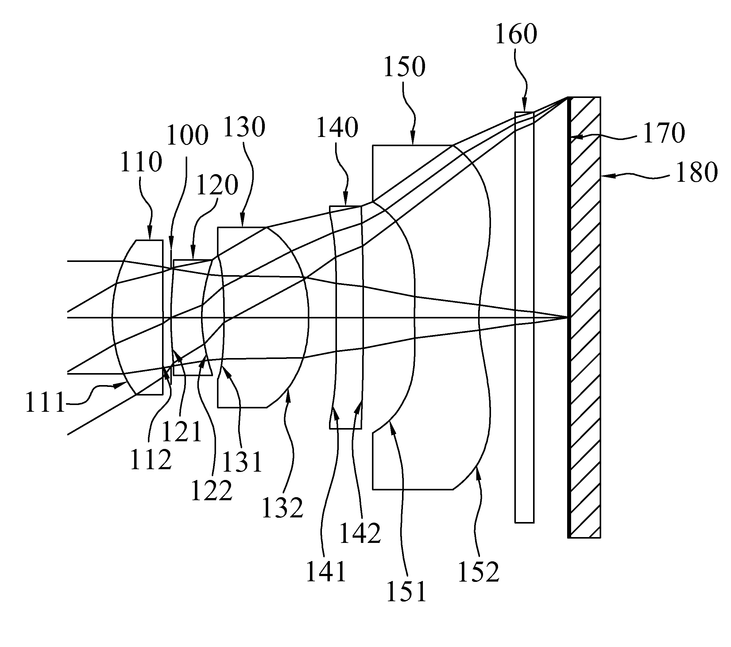
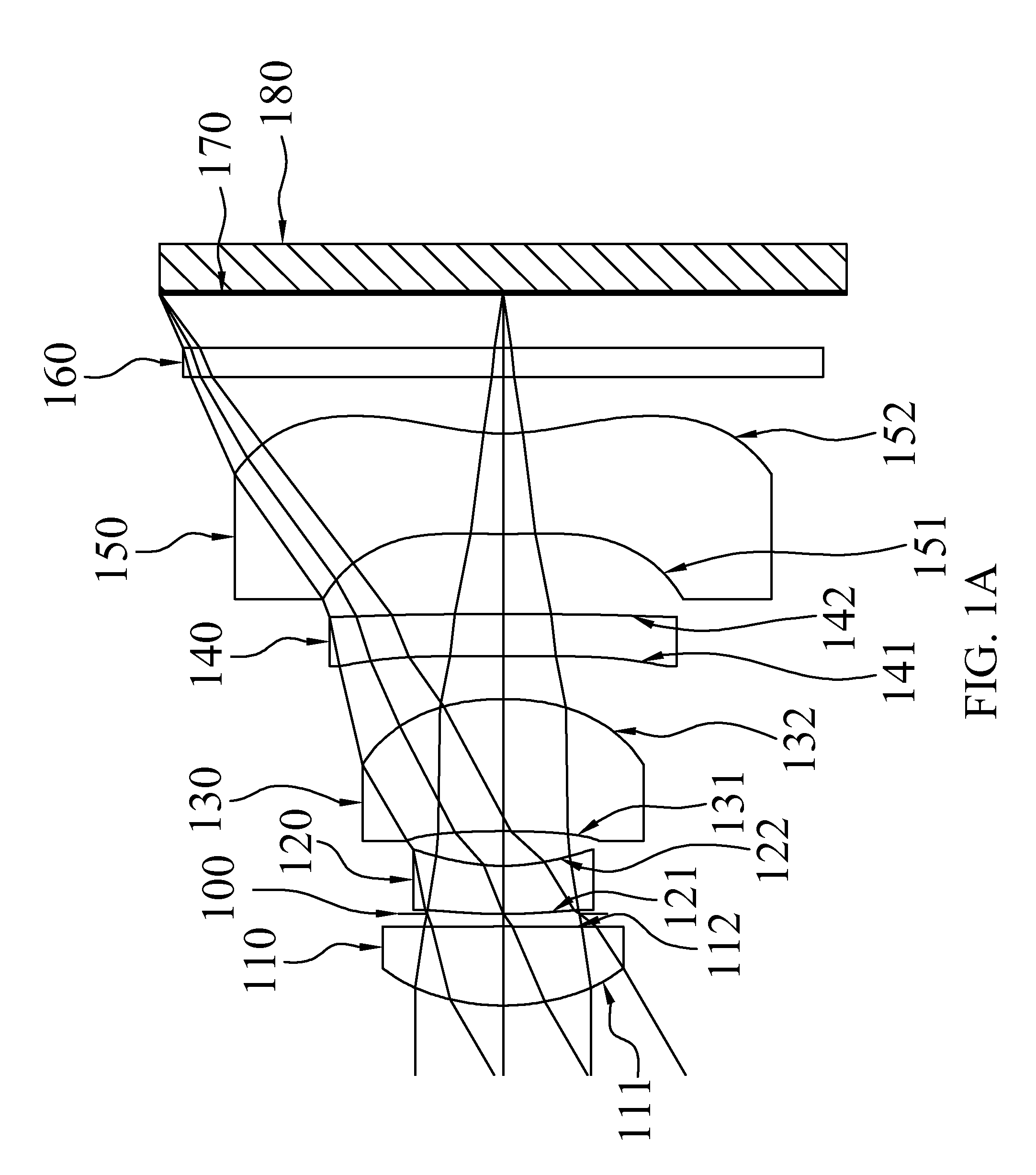
[0040]With reference to FIG. 1A for an optical imaging lens assembly of the present invention, the optical imaging lens assembly, sequentially arranged from an object side to an image side along an optical axis, comprises: the first lens element 110, the second lens element 120, the third lens element 130, the fourth lens element 140 and the fifth lens element 150, wherein the first lens element 110 with positive refractive power has a convex object-side surface 111; the second lens element 120 with negative refractive power has a convex object-side surface 121 and a concave image-side surface 122; the third lens element 130 with positive refractive power has a convex image-side surface 132; the fourth lens element 140 with refractive power has both object-side surface 141 and image-side surface 142 being aspheric; and the fifth lens element 150 with refractive power has a concave image-side surface 152 and both object-side surface 151 and image-side surface 152 being aspheric. The ...


PUM


Abstract

An optical imaging lens assembly, sequentially arranged from an object side to an image side along an optical axis, comprising: the first lens element with positive refractive power having a convex object-side surface, the second lens element with negative refractive power having a convex object-side surface and a concave image-side surface, the third lens element with positive refractive power having a convex image-side surface, the fourth lens element with refractive power having both optical surfaces being aspheric, the fifth lens element with refractive power having a concave image-side surface and both optical surfaces being aspheric, wherein a stop and an image sensor disposed on an image plane are also provided. By such arrangements, the image pickup optical system satisfies conditions related to shorten the total length and to reduce the sensitivity for use in compact cameras and mobile phones with camera functionalities.

Description

CROSS-REFERENCE TO RELATED APPLICATION[0001]This application claims the benefit of priority to Taiwan Patent Application No. 100122689, filed on Jun. 28, 2011, in the Taiwan Intellectual Property Office, the disclosure of which is incorporated herein in its entirety by reference.BACKGROUND OF THE INVENTION[0002]1. Field of the Invention[0003]The present invention relates to an optical imaging lens assembly, and more particularly to the optical imaging lens assembly to shorten total length and lower cost for applying to electronic products.[0004]2. Description of the Related Art[0005]In compact electronic products such as digital still cameras or mobile phone cameras, an optical imaging lens assembly is generally installed for capturing images of an object, and the optical imaging lens assembly tends to be developed with a compact design and a low cost, while meeting the user requirements of good aberration correction ability, high resolution, and high image quality.[0006]In general,...

Claims


Application Information

Patent Timeline
Patent Type & Authority Patents(United States)
IPC IPC(8): G02B9/60
CPCG02B13/0045G02B13/18G02B9/60
Inventor HUANG, HSIN-HSUAN
Owner LARGAN PRECISION
Why Eureka
Try Eureka