Valve timing controller for internal combustion engine

a timing controller and internal combustion engine technology, applied in the direction of valve drives, machines/engines, couplings, etc., can solve the problems of obstructing the swinging of the second rotating body, difficult to lock the valve timing at a specific phase, and remaining hydraulic oil, so as to achieve the effect of low necessity for discharging hydraulic oil from the hydraulic pressure chamber and high necessity for swinging the second rotating body

Inactive Publication Date: 2013-11-12
TOYOTA JIDOSHA KK
View PDF10 Cites 4 Cited by
  • Summary
  • Abstract
  • Description
  • Claims
  • Application Information

AI Technical Summary

Benefits of technology

[0007]Accordingly, it is an object of the present invention to provide a valve timing controller for an internal combustion engine that can readily discharge the hydraulic oil remaining in a hydraulic pressure chamber when the engine is stopped.
[0018]As described above, when the valve timing is not locked at a specific phase as the engine stops, the valve timing is often gradually retarded due to the influence of cam friction or the like. Thus, for example, in a variable mechanism in which the specific phase is set at the most retarded phase, the necessity for discharging hydraulic oil from the hydraulic pressure chamber becomes low. In a variable mechanism in which the specific phase is set at an intermediate phase between the most advanced phase and the most retarded phase, the necessity for swinging the second rotation body becomes high. Thus, in a variable mechanism in which the specific phase is set at the intermediate phase, hydraulic oil is readily discharged from the hydraulic pressure chamber. This further prominently obtains the advantages described above.

Problems solved by technology

However, when the engine is started, if a large amount of hydraulic oil is remaining in the hydraulic pressure chambers of the variable mechanism, the remaining hydraulic oil obstructs the swinging of the second rotating body.
It is thus difficult to lock the valve timing at a specific phase by using fluctuation of the cam torque to swing the second rotating body as described above.

Method used


Image

  • Valve timing controller for internal combustion engine
  • Valve timing controller for internal combustion engine
  • Valve timing controller for internal combustion engine

Examples


Embodiment Construction

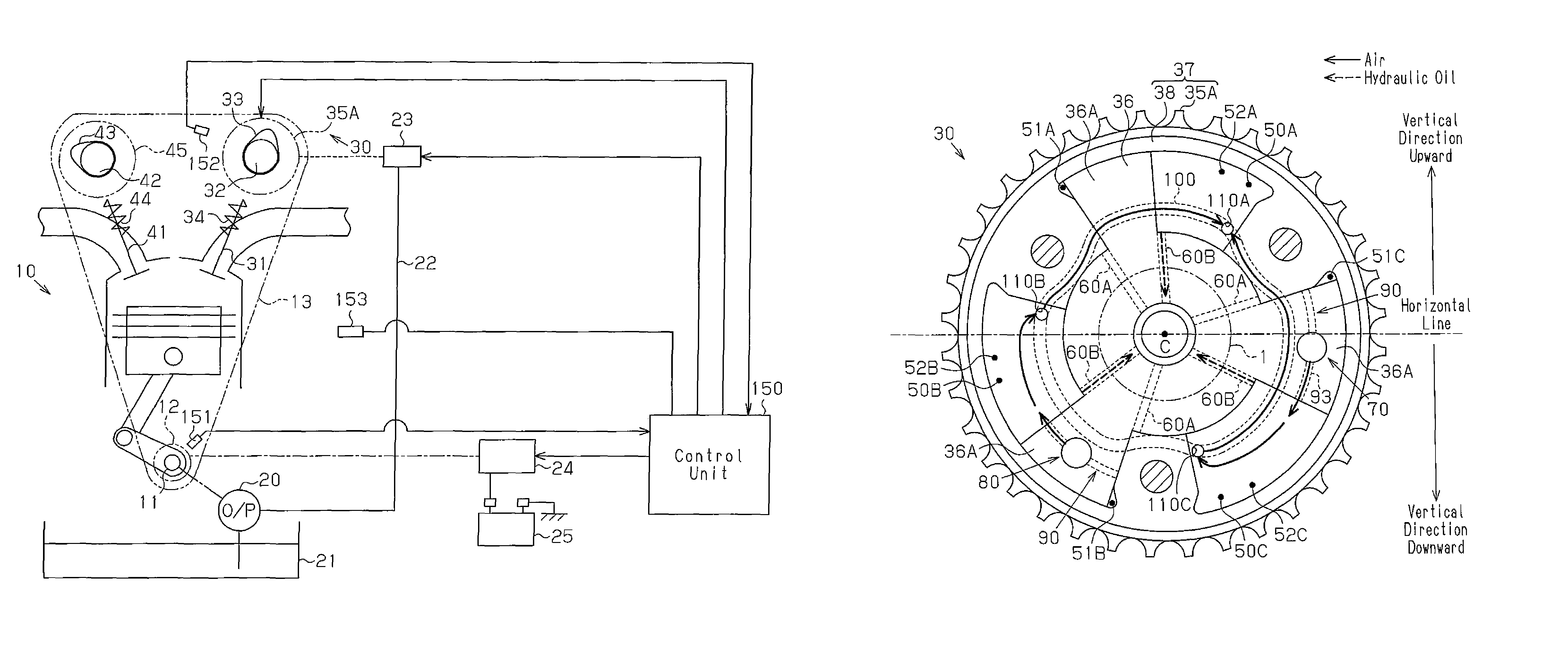
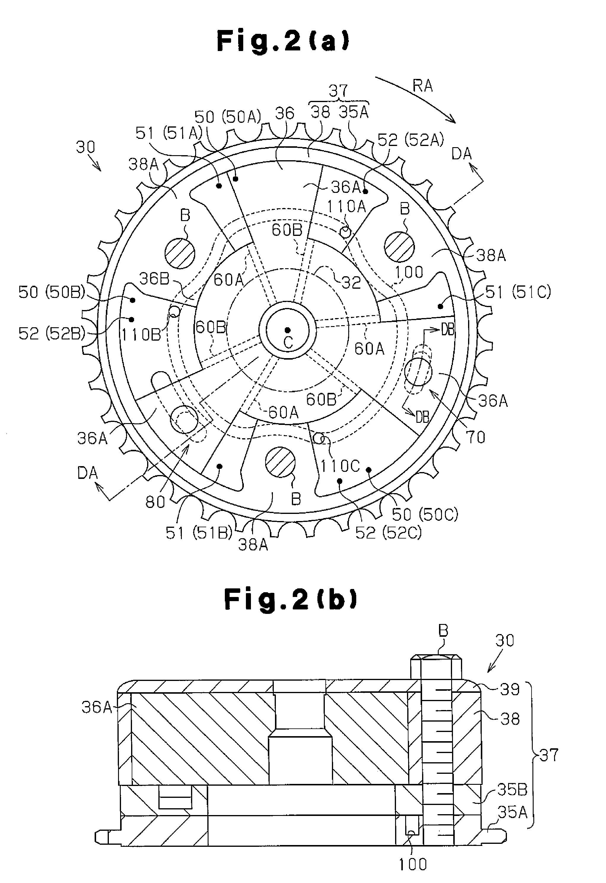
[0026]The overall structure of a valve timing controller will now be described with reference to FIG. 1. The valve timing controller controls the valve timing of an intake valve 31.

[0027]As shown in FIG. 1, an intake camshaft 32, which opens and closes the intake valve 31, and an exhaust camshaft 42, which opens and closes an exhaust valve 41, are arranged to be rotatable above an internal combustion engine 10. The intake camshaft 32 includes a variable mechanism 30 that varies the valve timing of the intake valve 31. A sprocket 35A of the intake camshaft 32, a sprocket 45 of the exhaust camshaft 42, and a sprocket 12 of a crankshaft 11 in the variable mechanism 30 are driven and coupled by a timing chain 13. Thus, when the crankshaft 11 is rotated, the torque is transmitted to the sprockets 35A and 45 by the timing chain 13 thereby rotating the intake camshaft 32 and the exhaust camshaft 42.

[0028]An intake valve spring 34 urges the intake valve 31 in a valve closing direction. When...


PUM


Abstract

A profile of a cam (33) of a camshaft (32) is set based on a relationship of a stop position of a vane rotor (36) at a most retarded phase relative to a housing rotor (37). In other words, the profile of the cam (33) arranged in the camshaft (32) is set so that a second opening (110B) of a communication passage (100), which opens in a second retardment chamber (52B), is located upward in a vertical direction from the axis C of the camshaft (32) when the camshaft (32) is at a neutral position, that is, when torque applied from the cam (33) to the camshaft (32) is the smallest.

Description

CROSS REFERENCE TO RELATED APPLICATIONS[0001]This application is a National Stage of International Application No. PCT / JP2011 / 061450 filed May 18, 2011, the contents of all of which are incorporated herein by reference in their entirety.FIELD OF THE INVENTION[0002]The present invention relates to a valve timing controller for an internal combustion engine that controls valve timing in accordance with an engine operation state.BACKGROUND OF THE INVENTION[0003]Patent document 1 describes an example of a known valve timing controller of the internal combustion engine. Such a valve timing controller, including that described in patent document 1, is provided with a variable mechanism including a first rotating body, which moves in cooperation with a crankshaft, and a second rotating body, which moves in cooperation with a camshaft. The variable mechanism supplies and discharges hydraulic oil to and from a plurality of hydraulic pressure chambers defined by the rotating bodies to relativ...

Claims


Application Information

Patent Timeline
Patent Type & Authority Patents(United States)
IPC IPC(8): F01L1/34
CPCF01L1/08F01L1/3442F01L2001/34423F01L2001/34453F01L2800/03
Inventor KIKUOKA, SHINICHIRONUMAKURA, MASAKI
Owner TOYOTA JIDOSHA KK
Why Eureka
Try Eureka