Drive roller for flat belts

a technology of flat belts and drive rollers, which is applied in the direction of highways, highway maintenance, hoisting equipment, etc., can solve the problems of only partially effective designs and extensive slipping, and achieve the effect of improving the characteristics of belt traction

Active Publication Date: 2013-11-12
DEERE & CO
View PDF41 Cites 36 Cited by
  • Summary
  • Abstract
  • Description
  • Claims
  • Application Information

AI Technical Summary

Benefits of technology

[0006]Another object of the invention is the provision of a drive roller that is effective to remove and / or prevent the accumulation of extraneous material between the drive roller and the belt.
[0010]In general, drive roller for flat belts is provided in various embodiments wherein the roller has improved characteristics for maintaining traction of belts, such as lagging applied to the roller.

Problems solved by technology

A problem exists when driving a flat belt with a drive roller when contamination is present.
Particularly, problematic with agricultural balers is an accumulation of wet organic material (wet silage) which creates a ‘slime’ layer between the drive roller and the flat belt that can lead to extensive slipping.
This problem is aggravated by the fact that the wet organic material also has a tendency to adhere to the belts and rollers.
However, these designs are only partially effective, as measured decreases are apparent between clean and contaminated samples.

Method used


Image

  • Drive roller for flat belts
  • Drive roller for flat belts
  • Drive roller for flat belts

Examples


Embodiment Construction

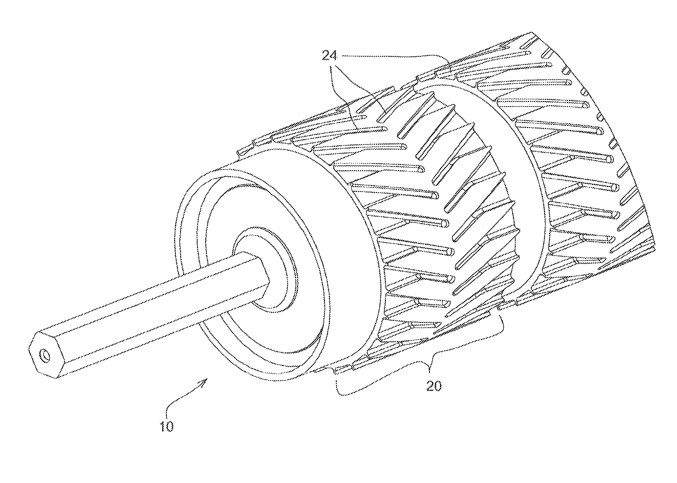
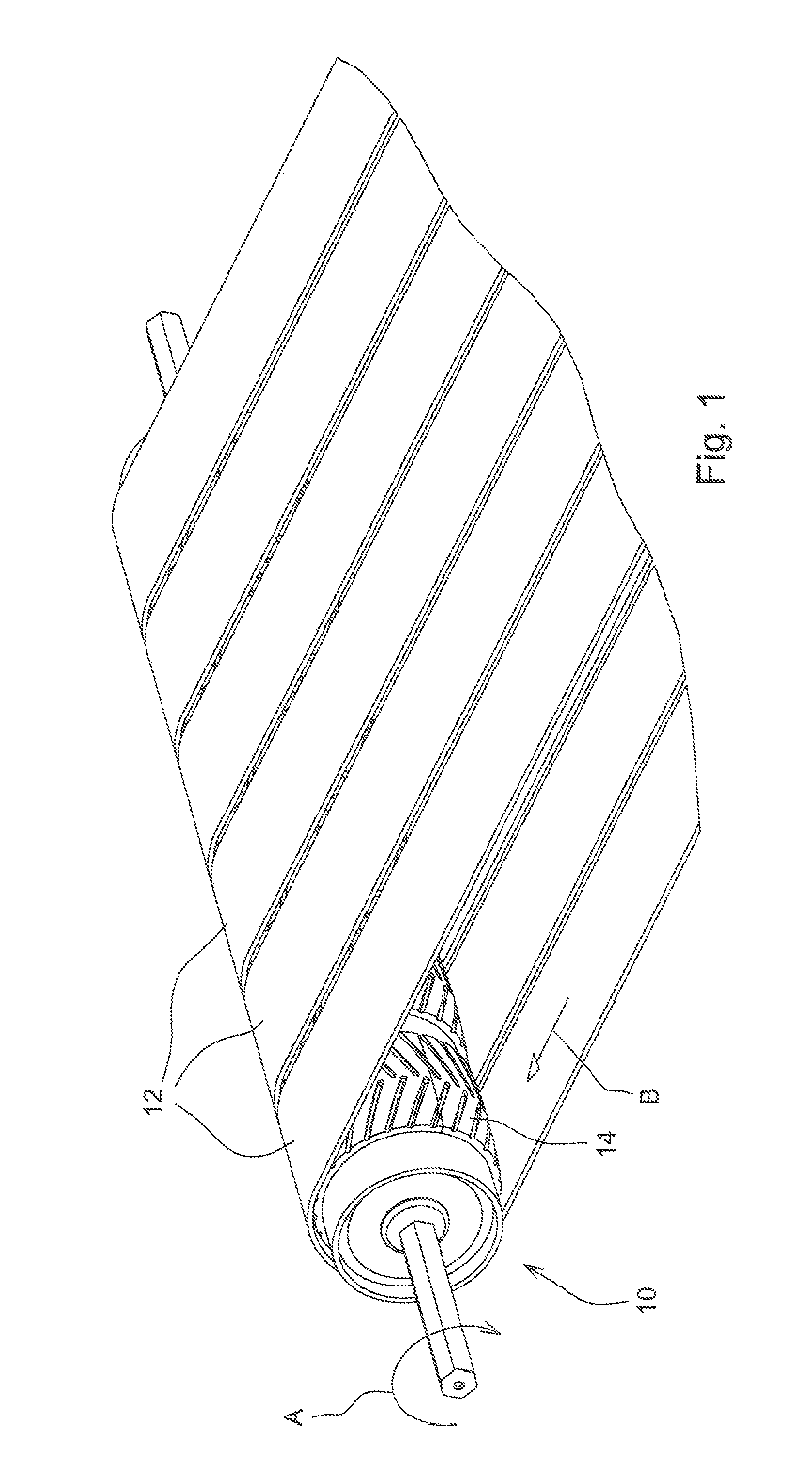
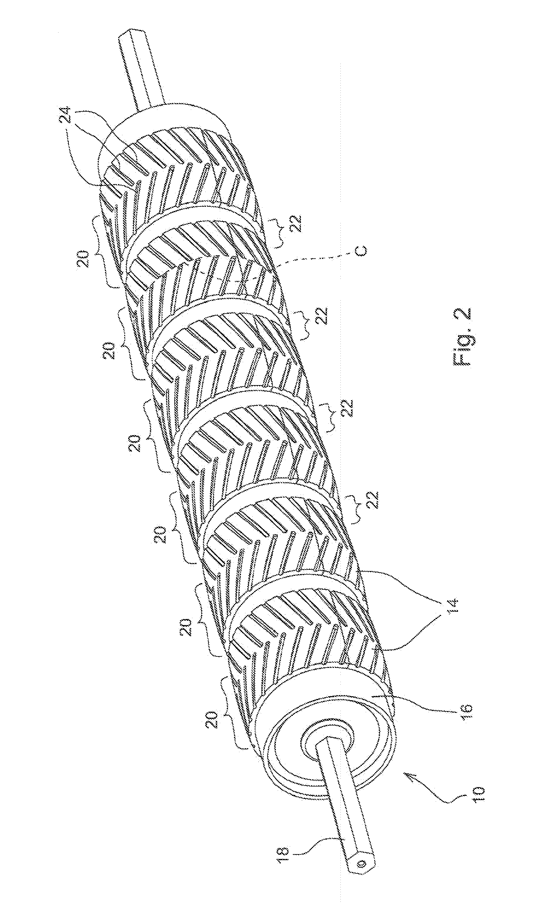
[0025]With reference now to the drawings and more particularly to FIGS. 1 and 2, it can be seen that one embodiment of a drive roller according to the invention is designated generally by the numeral 10. As shown in FIG. 1, the drive roller 10 is illustrated in conjunction with a plurality of flat belts 12 in a configuration as might be found in an agricultural baler used for producing round or cylindrical crop bales. It can also be seen that lagging 14 has been applied to the drive roller 10 and that the belts 12 are tensioned and trained in an endless loop around the roller 10 and at least a second roller (not shown), so that each belt 12 is in frictional contact with the lagging 14. Thus as the drive roller 10 is rotated in the direction of the arrow A the belts 12 move in the direction of the arrow B. In FIG. 2 the drive roller 10 is illustrated without the belts and it can be seen that the drive roller 10 consists of a cylindrical roller body 16 which is supported on a continuo...


PUM

PropertyMeasurementUnit
widthaaaaaaaaaa
sizeaaaaaaaaaa
lengthaaaaaaaaaa

Abstract

A drive roller for flat belts is provided in various embodiments wherein the roller has improved characteristics for maintaining traction of belts, such as lagging applied to the roller.

Description

FIELD OF THE INVENTION[0001]The present invention relates generally to drive rollers for flat belts. More particularly, the present invention relates to such drive rollers used to drive flat belts in agricultural equipment such as round or cylindrical balers. Specifically, the present invention relates to such rollers which have improved characteristics for maintaining traction of belts such as lagging applied to the roller.BACKGROUND OF THE INVENTION[0002]A problem exists when driving a flat belt with a drive roller when contamination is present. Water, dust, or mud-like material can reduce the coefficient of friction between the drive roller and the flat belt. Particularly, problematic with agricultural balers is an accumulation of wet organic material (wet silage) which creates a ‘slime’ layer between the drive roller and the flat belt that can lead to extensive slipping. This problem is aggravated by the fact that the wet organic material also has a tendency to adhere to the bel...

Claims


Application Information

Patent Timeline
Patent Type & Authority Patents(United States)
IPC IPC(8): A01B29/00F16H55/36B65G23/04
CPCA01F15/18B65G15/50B65G39/071B65G39/073A01F2015/186
Inventor DERSCHEID, DANIEL ERIC
Owner DEERE & CO
Why Eureka
Try Eureka