Eureka AIR delivers breakthrough ideas for toughest innovation challenges, trusted by R&D personnel around the world.

Image capturing apparatus, method for controlling image capturing apparatus, and method for predicting photometric value

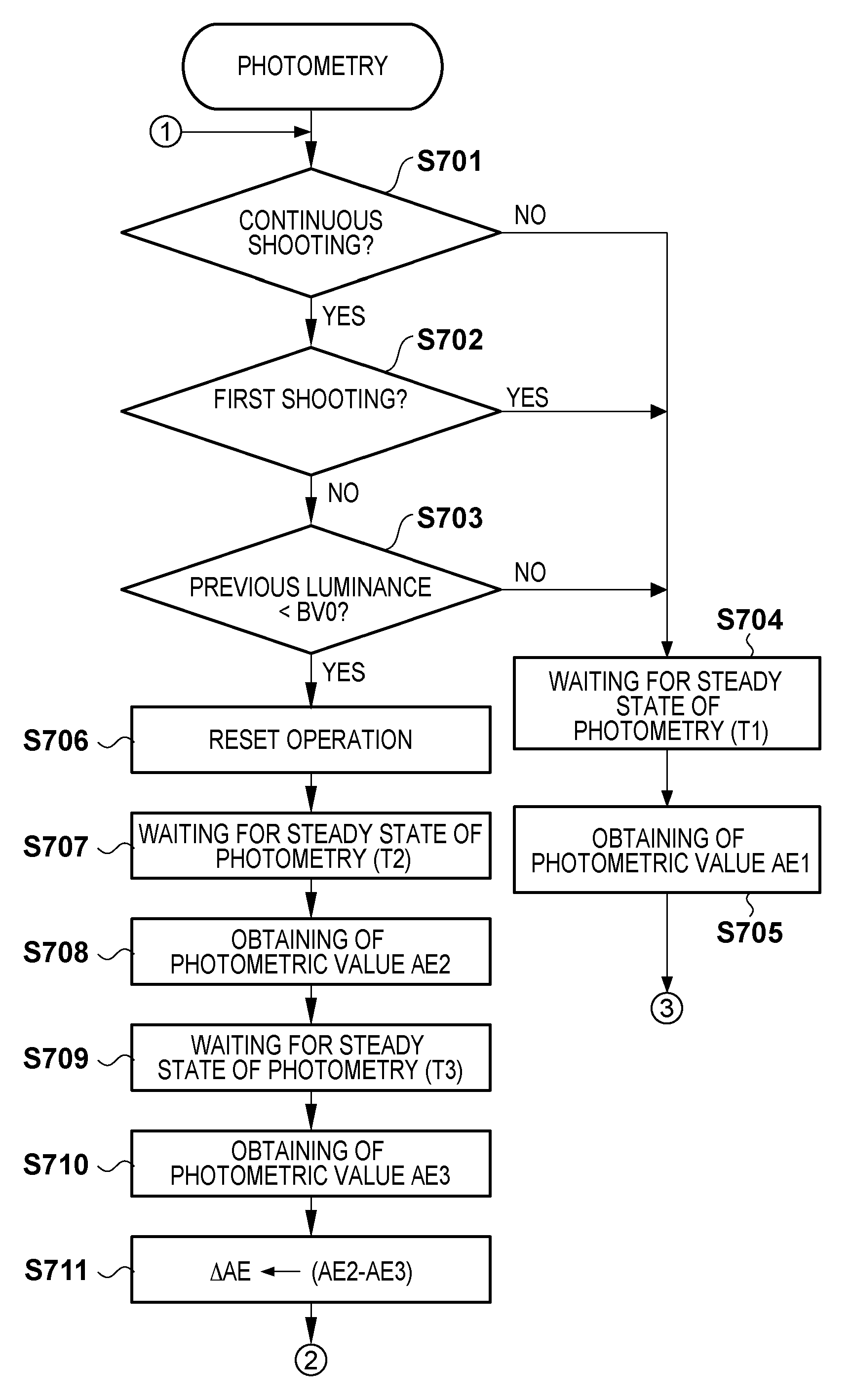
a technology of image capturing apparatus and image capturing apparatus, which is applied in the direction of exposure control, optical radiation measurement, instruments, etc., can solve the problems of increasing the release time lag, affecting the accuracy of photometric output, and taking a long time to obtain an accurate photometric output, so as to reduce the time required for photometry and achieve low luminance

Inactive Publication Date: 2013-11-12
CANON KK
View PDF6 Cites 0 Cited by
  • Summary
  • Abstract
  • Description
  • Claims
  • Application Information

AI Technical Summary

Benefits of technology

[0010]The present invention has been made in consideration of the above situation, and reduces the time required for photometry at low luminance.

Problems solved by technology

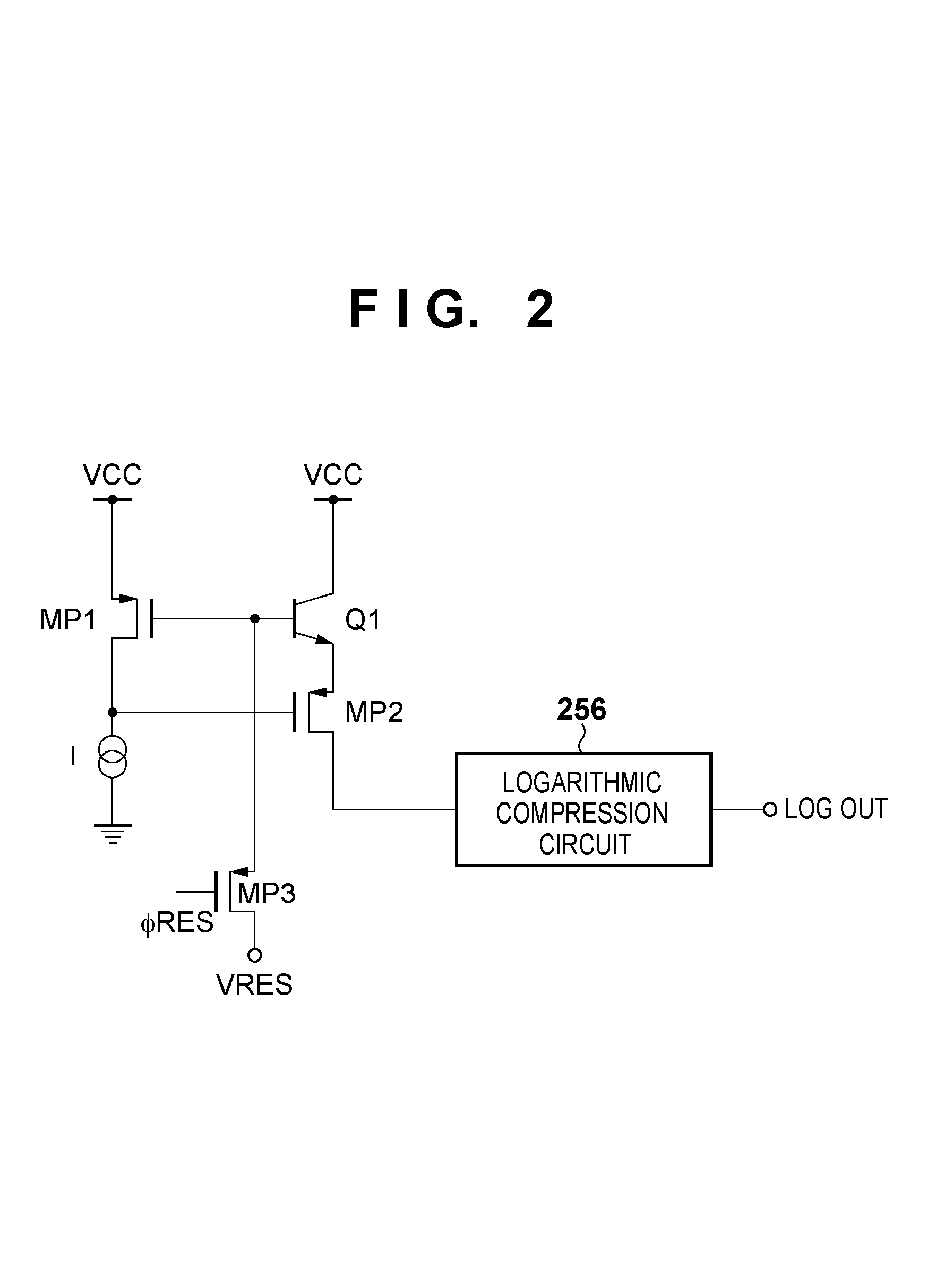
In the photometry circuit that utilizes the LOG characteristics, when a power supply voltage is turned on, it takes a long time (steady-state waiting time) to obtain an accurate photometric output after receiving light reflected from the subject, particularly at low luminance where the photo current is very small.
Also, in a system (particularly, a single-lens reflex camera) in which a mirror is retracted during shooting so that light to the photodiode is blocked, a degradation in photometric performance due to light response at low luminance leads to a considerably significant problem, such as an increase in release time lag, a decrease in continuous shooting speed, and the like.
In the technique described in Japanese Patent Laid-Open No. 2005-077938, however, the difference between the preliminary current and the photo current causes an error, and therefore, in order to compensate for the error, a compensation circuit is required, and the circuit size disadvantageously increases.
Also in the technique described in Japanese Patent Laid-Open No. 2008-309732, the difference between the photo current generated by preliminary irradiation and the photo current during photometry causes an error.
Further, the requirement of the light emitting device for preliminary irradiation disadvantageously increases the cost, the mounting area, and the like.

Method used


Image

  • Image capturing apparatus, method for controlling image capturing apparatus, and method for predicting photometric value
  • Image capturing apparatus, method for controlling image capturing apparatus, and method for predicting photometric value
  • Image capturing apparatus, method for controlling image capturing apparatus, and method for predicting photometric value

Examples


Embodiment Construction

[0024]Exemplary embodiments of the present invention will be described in detail in accordance with the accompanying drawings.

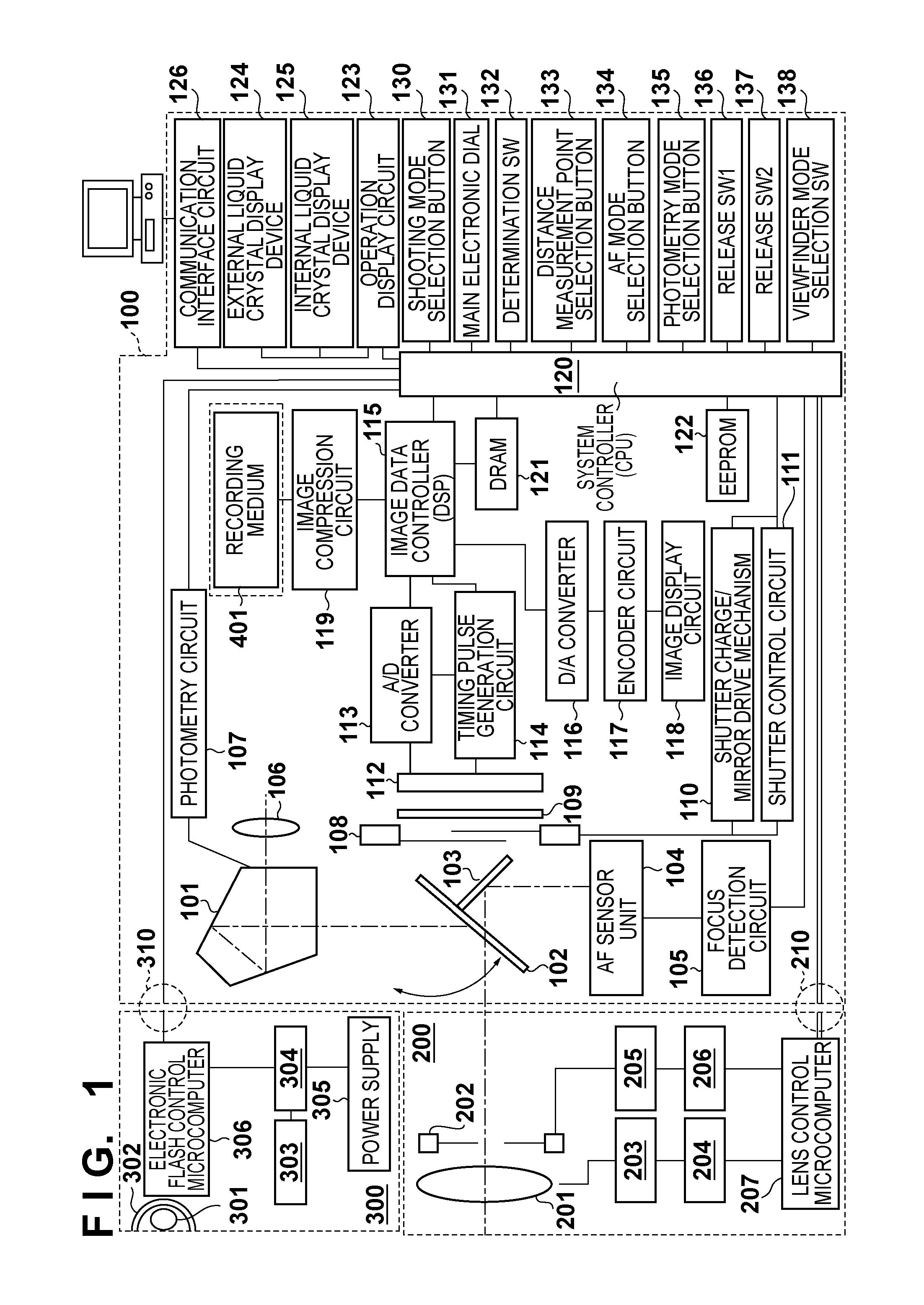
[0025]FIG. 1 is a block diagram schematically showing a configuration of a single-lens reflex type digital camera system according to an embodiment of the present invention. As shown in FIG. 1, in the digital camera system of this embodiment, a shooting lens unit 200 is detachably attached via a lens mount (not shown) to a camera body 100. A mount portion has an electrical connection point group 210. The connection point group 210 has a function of transferring a control signal, a status signal, a data signal, and the like between the camera body 100 and the shooting lens unit 200 and a function of supplying currents having different voltages. The connection point group 210 also has a function of transmitting a signal to a system controller 120 when the shooting lens unit 200 is connected to the camera body 100. As a result, the camera body 100 can communicat...


PUM


Abstract

An image capturing apparatus comprises: a photometry unit configured to perform photometry on a subject and output a photometric value; an obtaining unit configured to obtain a plurality of photometric values from the photometry unit during a predetermined period of time; and a calculation unit configured to perform a prediction calculation to predict a luminance of the subject based on the plurality of photometric values obtained by the obtaining unit.

Description

BACKGROUND OF THE INVENTION[0001]1. Field of the Invention[0002]The present invention relates to image capturing apparatuses, a method controlling the image capturing apparatus, and a method for predicting photometric values. More particularly, the present invention relates to image capturing apparatuses and methods for predicting photometric values in which the time required for photometry at low luminance is reduced.[0003]2. Description of the Related Art[0004]For image capturing apparatuses such as single-lens reflex cameras etc., a photometric sensor is widely used, which senses the photo current of a photodiode using the LOG characteristics of a diode or the like to measure the luminance of a subject within a wide dynamic range.[0005]In the photometry circuit that utilizes the LOG characteristics, when a power supply voltage is turned on, it takes a long time (steady-state waiting time) to obtain an accurate photometric output after receiving light reflected from the subject, p...

Claims


Application Information

Patent Timeline
Patent Type & Authority Patents(United States)
IPC IPC(8): G03B7/00G03B7/08G03B7/083G03B7/093G03B7/28G03B17/02
CPCG01J1/4209G01J1/44G03B7/08G03B7/083
Inventor TANIGUCHI, HIDENORI
Owner CANON KK
Why Eureka
Eureka Blog
Learn More