
Determination method for actuation touch point pressure value of a friction shift element

a technology of friction shift element and actuation pressure value, which is applied in the direction of gearing, hoisting equipment, instruments, etc., can solve the problems of increasing the manufacturing cost of a transmission device, actuation pressure value cannot be adapted, and requirements can only be implemented to the desired extent, so as to achieve low cost, simple design, and low construction cost

Active Publication Date: 2013-11-12
ZF FRIEDRICHSHAFEN AG
View PDF34 Cites 10 Cited by
  • Summary
  • Abstract
  • Description
  • Claims
  • Application Information

AI Technical Summary

Benefits of technology

The present invention provides a method for adapting the actuation pressure of a frictionally engaged shift element based on its service life using a simple design, low cost, and limited space requirement. This is done by measuring the actual actuation pressure applied to the shift element and making a small adjustment to the target actuation pressure value to ensure proper functioning. This allows for easy and quick determination of the applied actuation pressure value without the need for costly and space-consuming sensors.

Problems solved by technology

However, these requirements can be implemented only to the desired extent when the touchpoint of a frictionally engaged shift element is known.
In addition, sensors arranged in the region of rotating components require construction space and increase the manufacturing cost of a transmission device.
Furthermore, the actuation pressure value cannot be adapted depending on the service life when there is a malfunction in the region of the sensors, whereby the servicing of a transmission device is increased to an undesired extent.

Method used

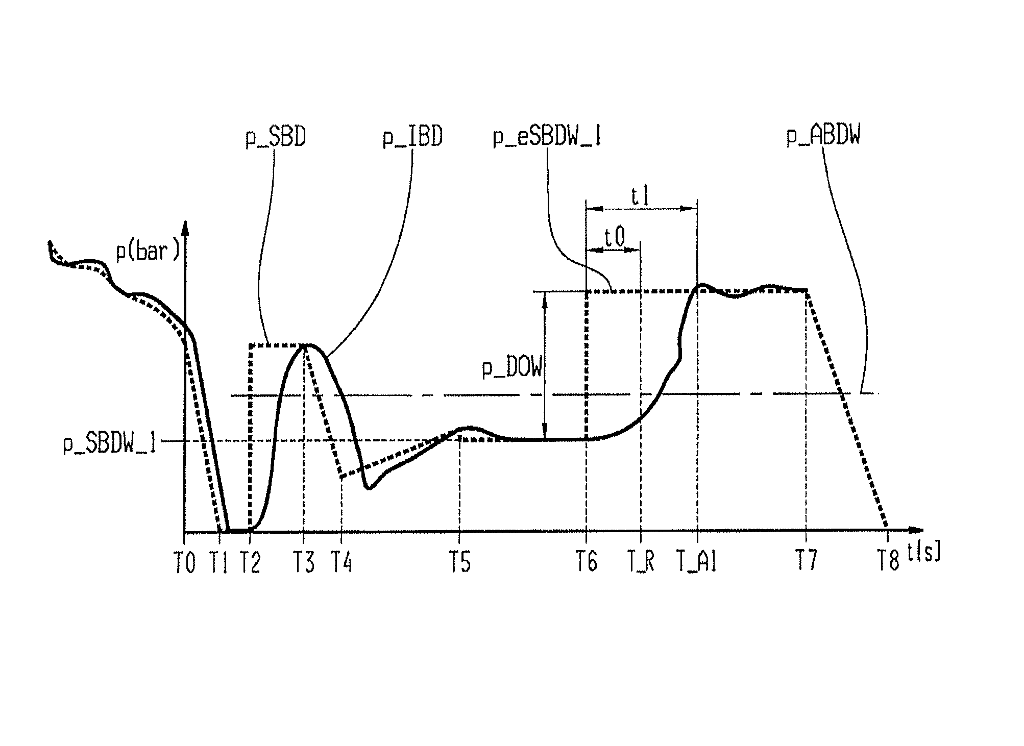
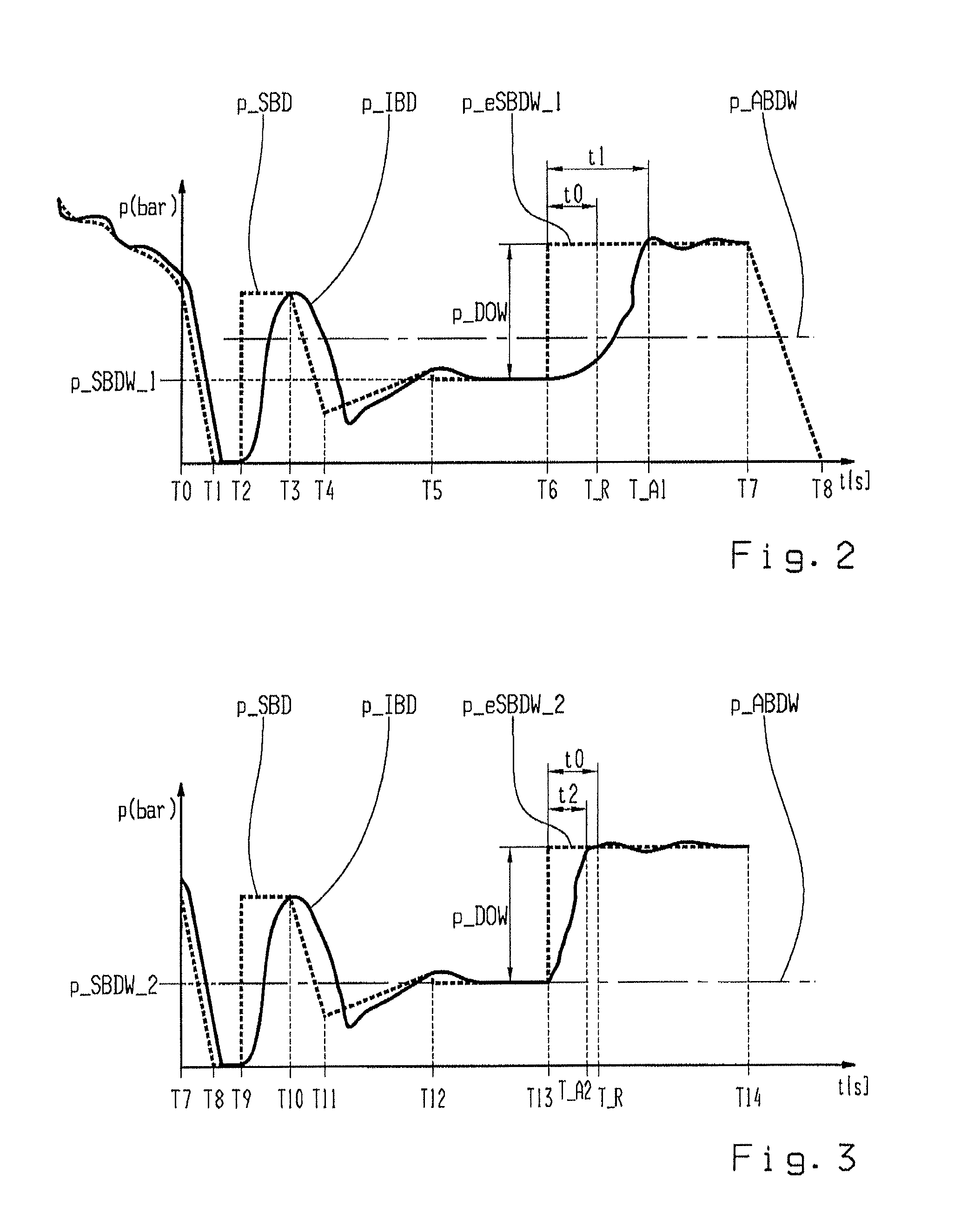

Image

  • Determination method for actuation touch point pressure value of a friction shift element
  • Determination method for actuation touch point pressure value of a friction shift element
  • Determination method for actuation touch point pressure value of a friction shift element

Examples


Embodiment Construction

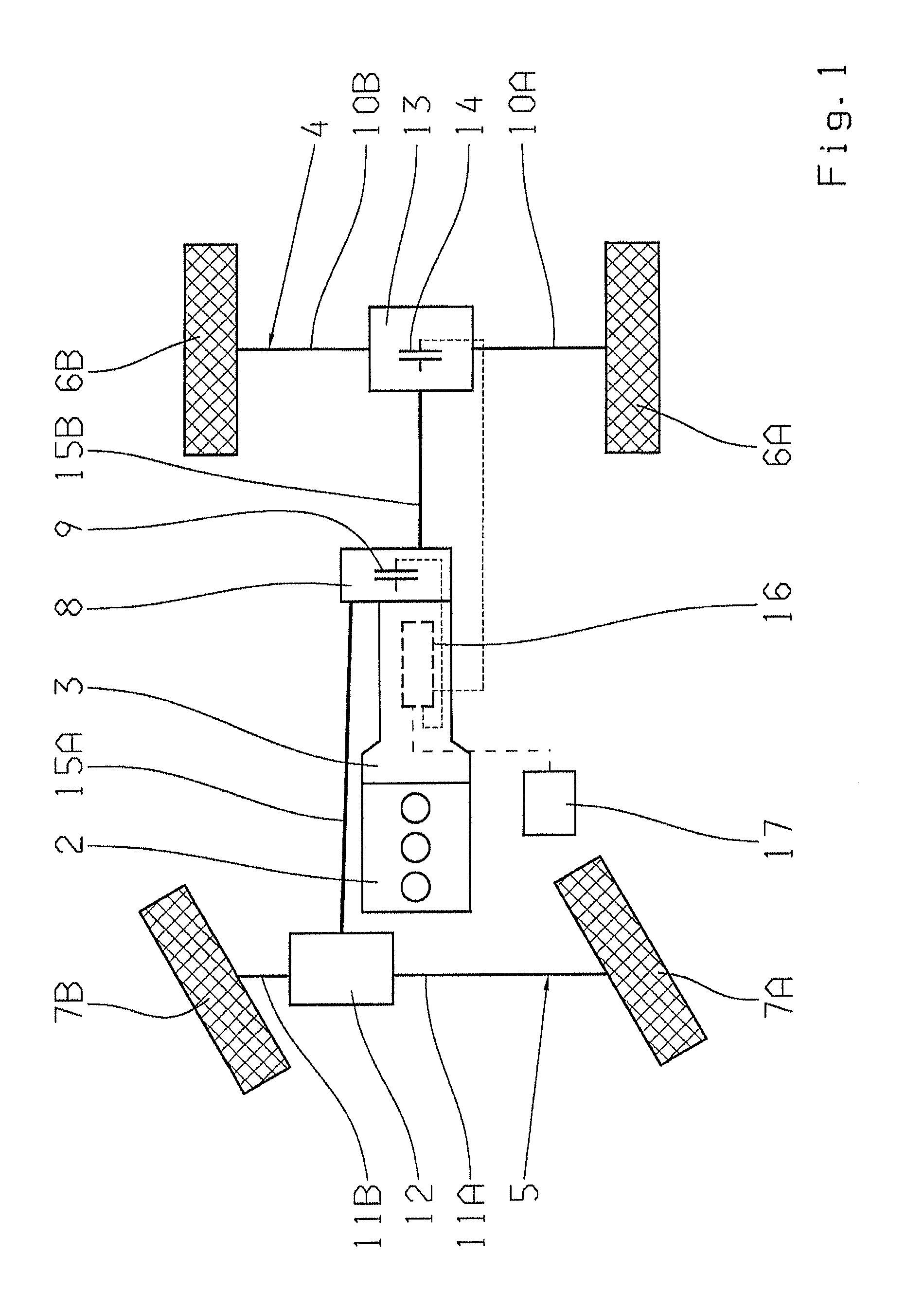
[0023]FIG. 1 is a highly schematic representation of a drive train 1 of an all-wheel drive vehicle. The drive train 1 comprises a drive motor 2 and a main gearbox 3 that can be any gearbox known from practical applications, and by means of which different transmission ratios for forward and reverse travel can be realized.

[0024]The drive train has two drivable vehicle axles 4, 5 that are equipped in a known manner with at least one drive wheel 6A, 6B and 7A, 7B on each side of the vehicle, and in which vehicle axle 4 is the vehicle rear axle in the present case and vehicle axle 5 is the vehicle front axle. Between the main gearbox and the vehicle axles 4, 5, a transmission device 8 designed as a longitudinal transfer case is disposed by means of which drive, torque of the drive motor 2 applied to an input shaft, not shown in the drawing, is distributed via a first longitudinal vehicle shaft 15A and a second longitudinal vehicle shaft 15B between the vehicle rear axle 4 and vehicle fr...


PUM


Abstract

A method of determining an applied actuation touch point pressure value of a frictionally engaged shift element of a transmission at which transmission, via the shift element, is approximately zero, and an increase in pressure relates to an increase of the power transmission via the shift element. The method includes supplying a predefined pressure to the shift element at which power transmission is zero. Increasing the target pressure by an offset pressure to transfer the shift element into a predefined operating state which initiates time monitoring. Determining a characteristic of the actual pressure. After a testing time, a monitoring period is compared with a reference period. When the monitoring period is less than or equal to the reference period, the applied pressure is set to be equivalent with the target pressure.

Description

[0001]This application claims priority from German patent application serial no. 10 2010 039 172.7 filed Aug. 11, 2010.FIELD OF THE INVENTION[0002]The invention relates to a method for determining an applied actuation pressure value of a frictionally engaged shift element of a transmission device.BACKGROUND OF THE INVENTION[0003]The transmission capability of a frictionally engaged shift element, for example a multi-disk clutch, multi-disk brake, etc., of a transmission device of a vehicle drive train, in particular a multi-stage automatic transmission or a transverse transfer case, or an all-wheel distributor clutch, can normally be varied by applying an actuation force between a minimum at which the frictionally engaged shift element is completely disengaged and the transmission capability is substantially zero, and a maximum at which the frictionally engaged shift element is substantially fully engaged and is in a slip-free operating state.[0004]In order to change the operating s...

Claims


Application Information

Patent Timeline
Patent Type & Authority Patents(United States)
IPC IPC(8): F16D48/06
CPCF16D48/066F16H61/061F16D2500/1026F16D2500/3024F16D2500/3166F16D2500/50251F16H2061/0087F16H2342/042
Inventor MARTIN, GERHARD HERMANNEBERHARD, WILFRIDUMMER, BERND
Owner ZF FRIEDRICHSHAFEN AG
Learn More