Floor cleaner scrub head having a movable disc scrub member

a technology of scrub head and disc, which is applied in the field of scrub head having a movable disc scrub member, can solve the problems of cumbersome inspection of scrub brushes and difficulty in visual positioning

Active Publication Date: 2013-11-19
TENNANT COMPANY
View PDF229 Cites 62 Cited by
  • Summary
  • Abstract
  • Description
  • Claims
  • Application Information

AI Technical Summary

Problems solved by technology

However, for some floor cleaners, particularly larger cleaners that include one or more scrub brushes that are centrally positioned beneath the cleaner, inspecting the scrub brushes can be cumbersome.
Additionally, the operator must often feel for the mechanism that releases the scrub member from the scrub head since it is difficult to visually locate it when lying underneath the cleaner.

Method used


Image

  • Floor cleaner scrub head having a movable disc scrub member
  • Floor cleaner scrub head having a movable disc scrub member
  • Floor cleaner scrub head having a movable disc scrub member

Examples


Embodiment Construction

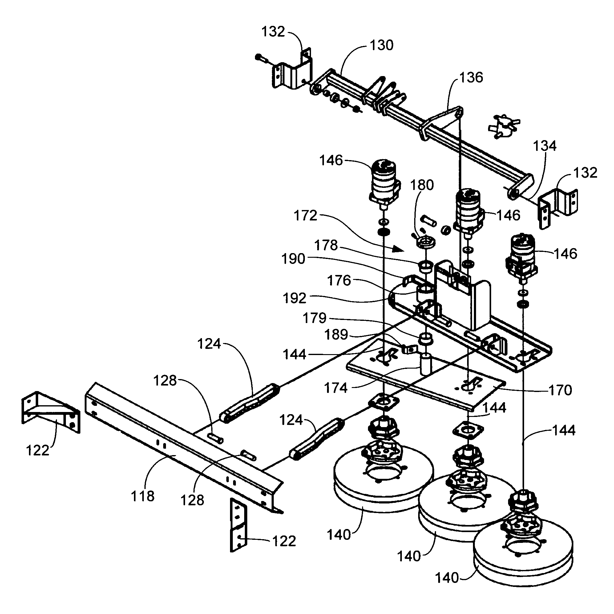
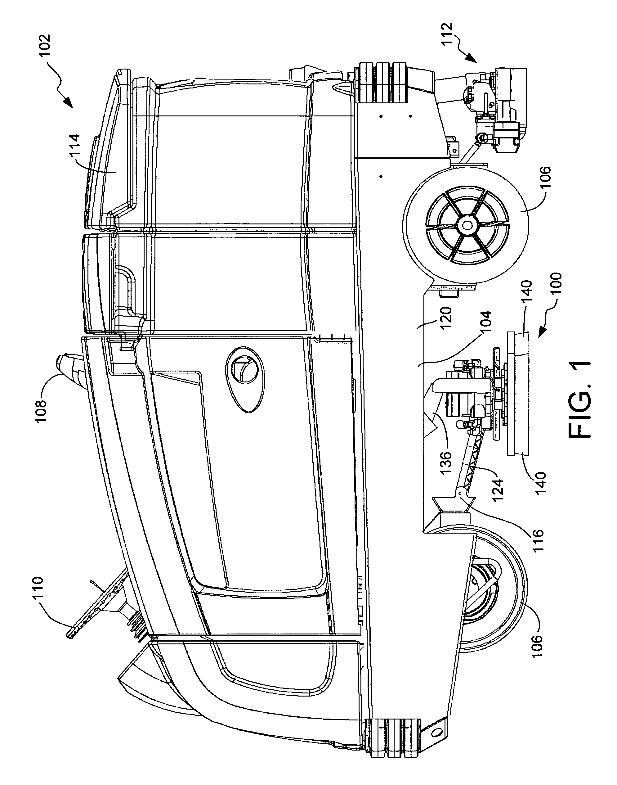
[0017]The present invention is generally directed to a scrub head 100 for use with an industrial floor cleaner, such as a ride-behind or walk-behind floor scrubber or sweeper / scrubber machine. FIG. 1 is a schematic diagram of an exemplary floor cleaner 102 in accordance with embodiments of the invention that includes the scrub head 100 with a side wall removed to expose the scrub head 100.

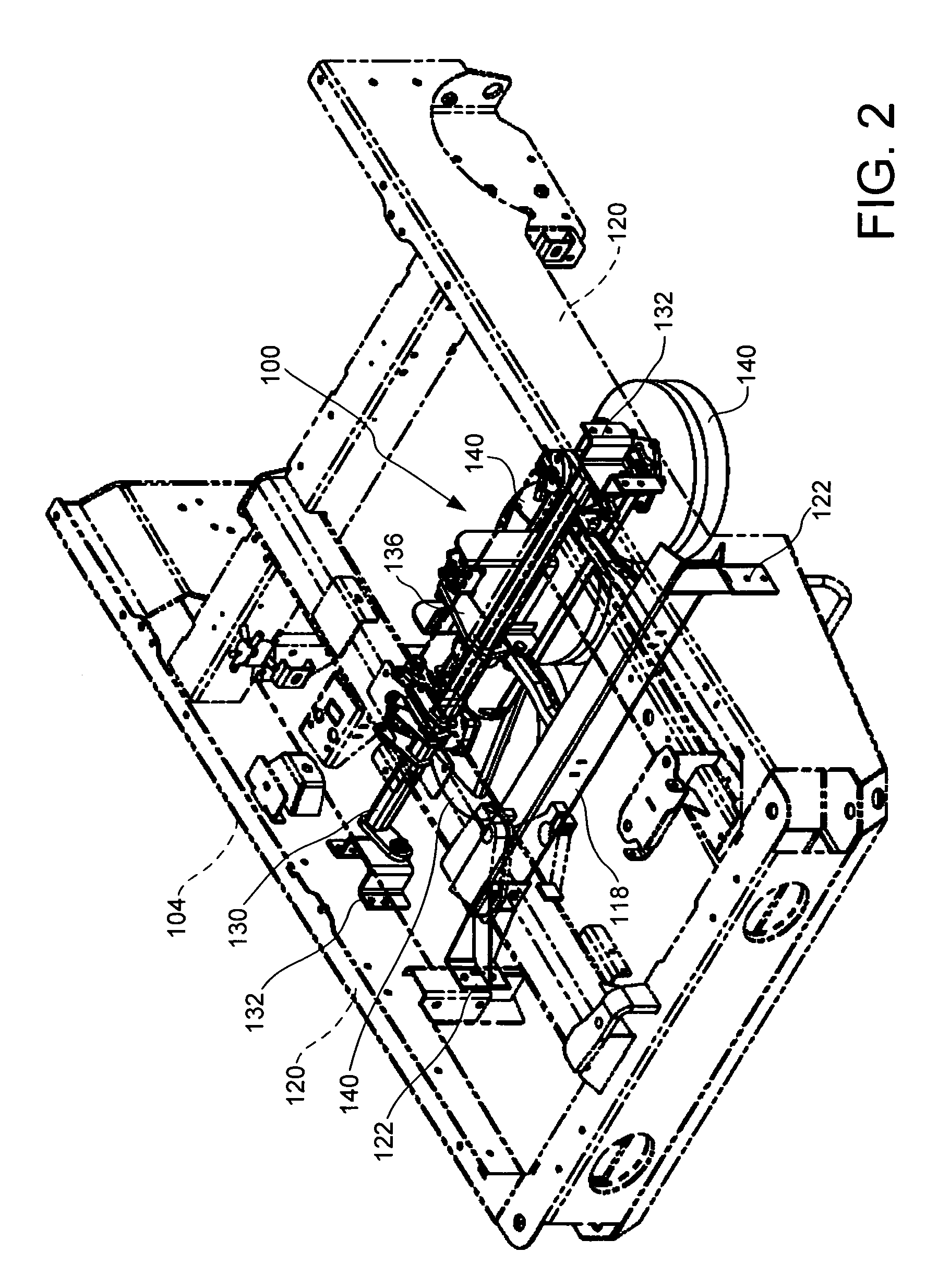
[0018]The floor cleaner 102 includes a mobile body having a frame 104 that supports the various machine components including the scrub head 100 of the present invention, as shown in FIG. 2. The frame 104 is supported on wheels 106. The wheels can include one or two steerable front wheels and two rear wheels, for example. The front or rear wheels 106 are driven by a motor in accordance with conventional methods. The cleaner 102 also includes a seat 108 for an operator, a steering wheel 110 and suitable controls. A vacuum pickup squeegee 112 is positioned behind the scrub head 100 and is used to remo...


PUM


Abstract

A scrub head includes a first disc scrub member, a movable support having first and second positions, and a movable disc scrub member. The first disc scrub member is rotatable about a first vertical axis. The movable disc scrub member is rotatable about a second vertical axis and is connected to the movable support. The movable disc scrub member is configured to move relative to the first disc scrub member along first and second orthogonal axes of a horizontal plane, which is transverse to the first and second vertical axes, between first and second positions respectively corresponding to the first and second positions of the movable support.

Description

FIELD OF THE INVENTION[0001]The present invention is generally directed to scrub heads of floor cleaners and, more particularly, to a scrub head having a movable disc scrub member.BACKGROUND OF THE INVENTION[0002]In the design of industrial floor cleaners, it is common to mount scrub members (i.e., scrub brushes or pads) and their drive motors in an assembly called a scrub head. The scrub head generally spans a width of the cleaner and can be mounted in front of, underneath amidships, or behind the machine frame. The scrub head is commonly attached in some articulated manner to the frame of the machine so that the scrub members can be raised for transport and lowered to the floor to perform cleaning operations.[0003]During floor cleaning operations, water or cleaning liquid is applied to the floor either in front of or at the scrub head. The scrub members scrub the wetted floor to remove dirt from the floor. A vacuumized squeegee, located behind the scrub head, operates to remove th...

Claims


Application Information

Patent Timeline
Patent Type & Authority Patents(United States)
IPC IPC(8): A47L11/283
CPCA47L11/283A47L11/4038A47L11/4055A47L11/4061
Inventor LORING, PETER ALEXANDER
Owner TENNANT COMPANY
Why Eureka
Try Eureka