
Carbon fiber wall reinforcement system and a method for its use

a technology of carbon fiber wall reinforcement and carbon fiber reinforcement, which is applied in the direction of cellars, foundation engineering, building repairs, etc., can solve the problems of material resistance to lateral forces that is very little, insufficient to counter strong lateral forces by itself, and begins to bow and crack

Active Publication Date: 2013-11-19
RHINO PROD USA
View PDF21 Cites 12 Cited by
  • Summary
  • Abstract
  • Description
  • Claims
  • Application Information

AI Technical Summary

Benefits of technology

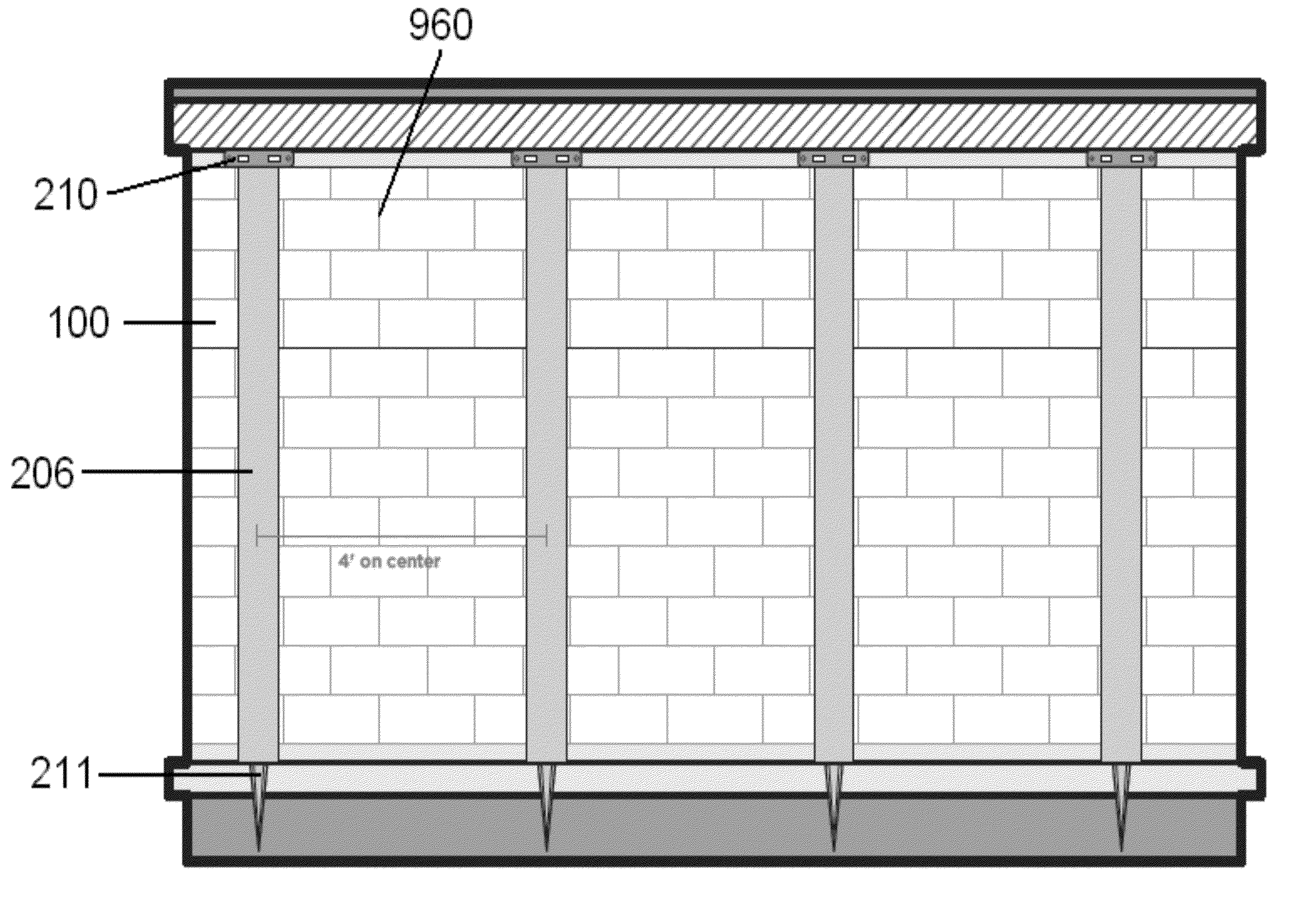
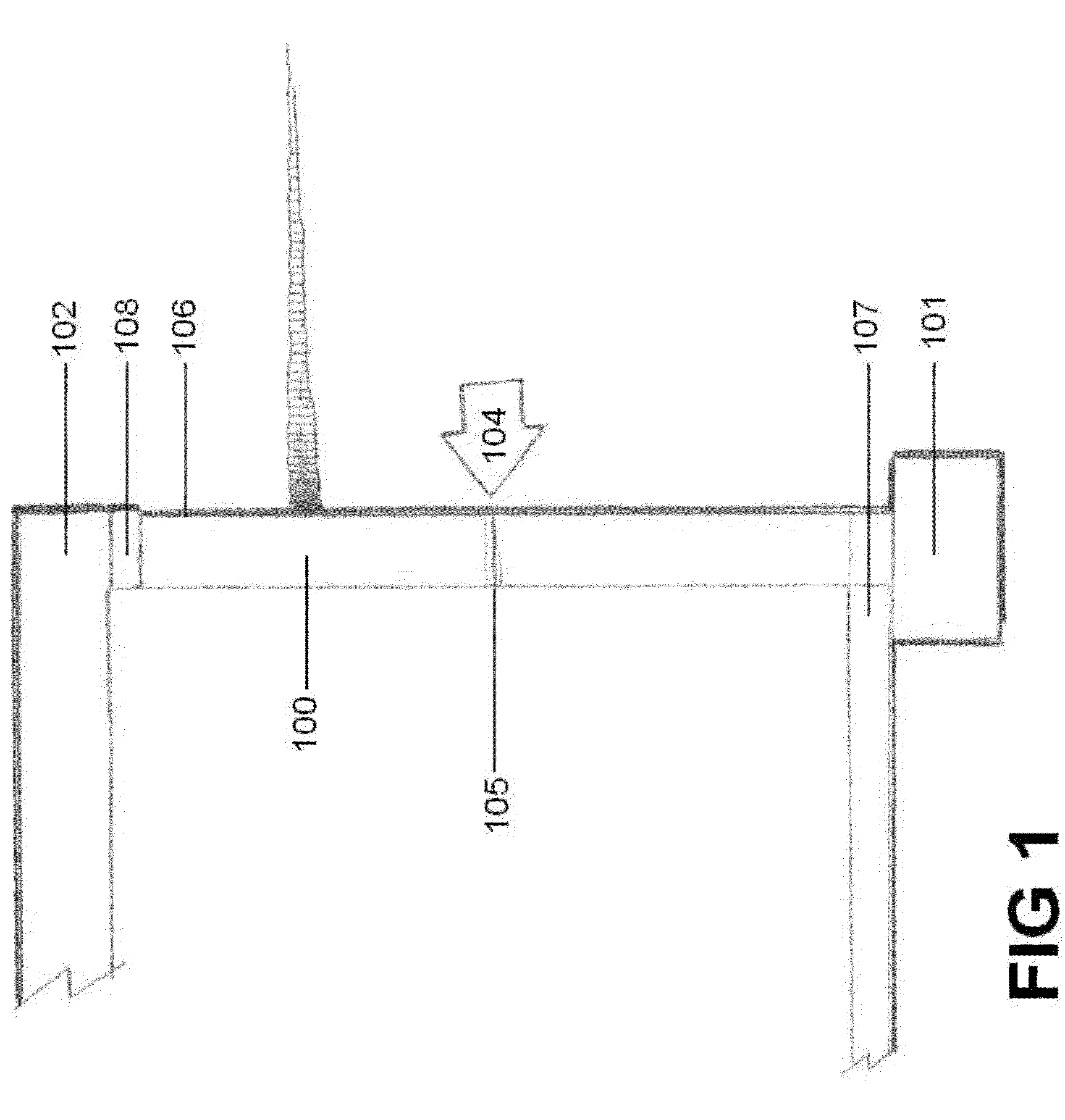
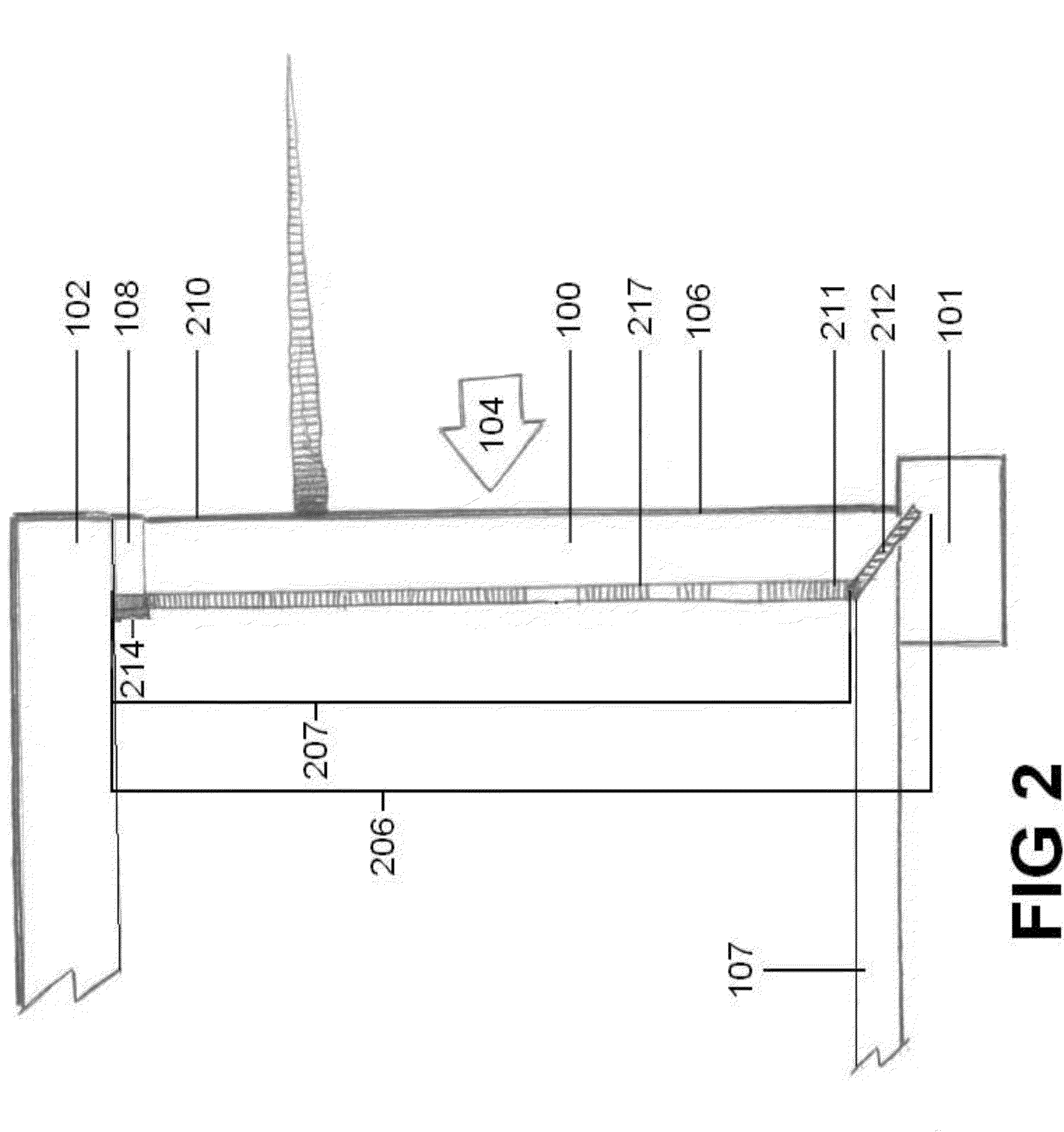
The present invention is about a system to reinforce a basement wall by using carbon fiber strips along with pins and a sill plate bracket assembly. This system can disperse lateral forces throughout the entire wall and is particularly useful in preventing damage to the basement wall during seismic events. The technical effect of this invention is better protection and reinforcement of basement walls to ensure safety and security.

Problems solved by technology

However, these materials provide very little resistance to lateral forces created by soil and water pushing against the outside surface of the wall.
However, in many instances, these walls cannot withstand the magnitude of these lateral forces and can begin to bow and crack.
This metal provides some resistance to lateral forces, but it is often insufficient to counter strong lateral forces by itself.
Additionally, these types of solutions cannot be installed after a wall has been constructed, and therefore, cannot be used to reinforce a wall after it has already been compromised by lateral forces.
However, steel beams can be large and unsightly when installed along a basement wall.
This can be unacceptable in finished basements, which are commonly found in modern homes and office buildings.
However, when carbon fiber is placed only on the surface of a wall, stress points can be created at the top and the bottom of the wall, where there continues to be no reinforcement.
This strap can reduce some of stress created at the top of the wall where the carbon fiber strip ends, but still allows shifting to occur and does not address the fact that there remains no support at the bottom of the wall.

Method used


Image

  • Carbon fiber wall reinforcement system and a method for its use
  • Carbon fiber wall reinforcement system and a method for its use
  • Carbon fiber wall reinforcement system and a method for its use

Examples


Embodiment Construction

[0023]This description of the exemplary embodiments is intended to be read in connection with the accompanying drawings, which are to be considered part of the entire written description. In the description, relative terms such as “lower,”“upper,”“horizontal,”“vertical,”, “above,”“below,”“up,”“down,”“top” and “bottom” as well as derivative thereof (e.g., “horizontally,”“downwardly,”“upwardly,” etc.) should be construed to refer to the orientation as then described or as shown in the drawing under discussion. These relative terms are for convenience of description and do not require that the apparatus be constructed or operated in a particular orientation. Terms concerning attachments, coupling and the like, such as “connected” and “interconnected,” refer to a relationship wherein structures are secured or attached to one another either directly or indirectly through intervening structures, as well as both movable or rigid attachments or relationships, unless expressly described othe...


PUM

PropertyMeasurementUnit
lengthaaaaaaaaaa
lengthaaaaaaaaaa
lengthaaaaaaaaaa

Abstract

The basement wall reinforcement system comprises carbon fiber materials securely mounted to the wall being reinforced as well as to structural components at both the top and bottom of the wall. These additional connections at the top and bottom of the wall increase the capacity of the carbon fiber to prevent bowing and cracking by transferring lateral forces from the wall to these structural components. Such structural components can include foundations, basement floors, sill plates, rim joists and floor joists. The carbon fiber can be connected to these structural components by pins, epoxies and specially designed brackets.

Description

CROSS REFERENCE TO RELATED APPLICATIONS[0001]This application claims benefit to provisional application No. 61 / 294,622, which is incorporated by reference herein in its entirety.FIELD OF THE INVENTION[0002]The present carbon fiber wall reinforcement system is an improvement over existing carbon fiber devices used to support basement and foundation walls and prevent bowing and cracking. While it is known that carbon fiber strips can be mounted on a basement wall to provide lateral support, the attachments used at the top and bottom of each carbon fiber strip must also provide sufficient force resistance to prevent failure at these locations. A woven carbon fiber pin or similar pin can be connected to the floor and foundation to provide support at that location and a sill plate bracket can be used at the top of the wall to provide reinforcement by connecting the carbon fiber strip to the sill plate or similar structural feature of the building.BACKGROUND[0003]The basement walls of any...

Claims


Application Information

Patent Timeline
Patent Type & Authority Patents(United States)
IPC IPC(8): E04B1/00
CPCE02D29/00E04B1/0007E04G23/0229E04B1/38E04B1/92E04G2023/0251E04G2023/0262
Inventor SECREST, ROBERT LUKE
Owner RHINO PROD USA
Learn More