Torque multiplier

a technology of torque multiplier and torque multiplier, which is applied in the field of torque multiplier, can solve the problems of inability to provide torque and the inability of the operator to identify if the bolt or nut is properly tightened, and achieve the effect of ensuring the operation quality of tightening/loosening bolts

Active Publication Date: 2013-11-19
LEGEND LIFESTYLE PRODS CORP
View PDF2 Cites 10 Cited by
  • Summary
  • Abstract
  • Description
  • Claims
  • Application Information

AI Technical Summary

Benefits of technology

[0009]The effectiveness of the torque multiplier is that the torque sensor is mounted to the torque input shaft to precisely detect the torque value. Further, the angle sensor is mounted to the main body to precisely detect the angle value. Further, these data of the torque value and angle value are transmitted by an information transmission circuit, in a wired or wireless fashion, to an electronic device, such as a personal computer, a notebook computer, a mobile phone, and a personal digital assistant (PDA), for storage, display and use, whereby a user may directly access the data of torque value and angle value obtained in the torque multiplier through a handy electronic device in order to ensure the operation quality of tightening / loosening bolts and nuts.

Problems solved by technology

In the above-discussed known torque multiplier and other prior art devices, these devices provide only a function of multiplying the output torque, and they are not capable of providing torque level and horizontal angle to be referenced by a tool operator, whereby there is still the problem of manual error that is caused by improper operation and leads to damage and breaking of bolts or nuts and also, there is no way for an operator to identify if a bolt or nut is properly tightened.

Method used


Image

  • Torque multiplier
  • Torque multiplier
  • Torque multiplier

Examples


first embodiment

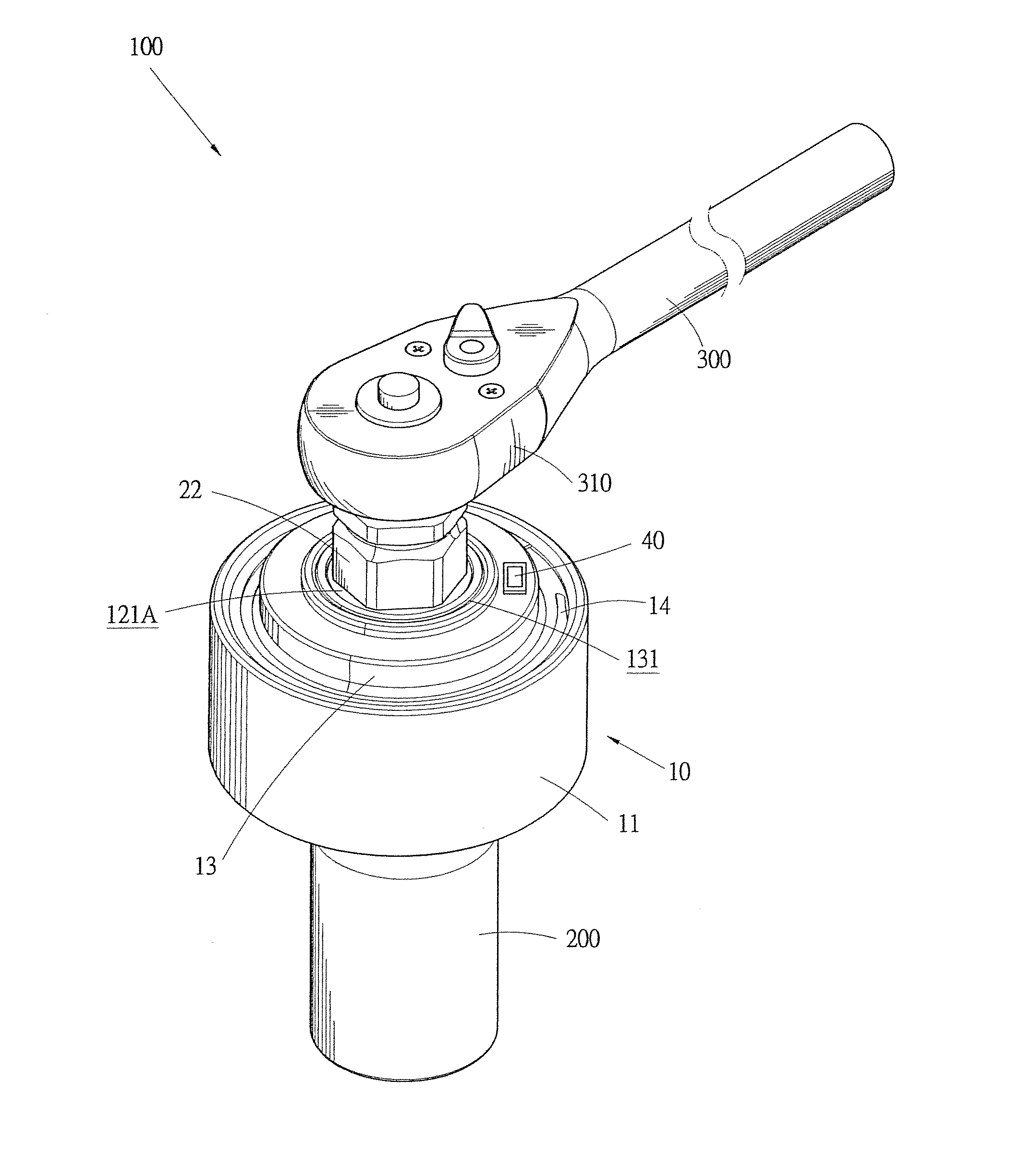
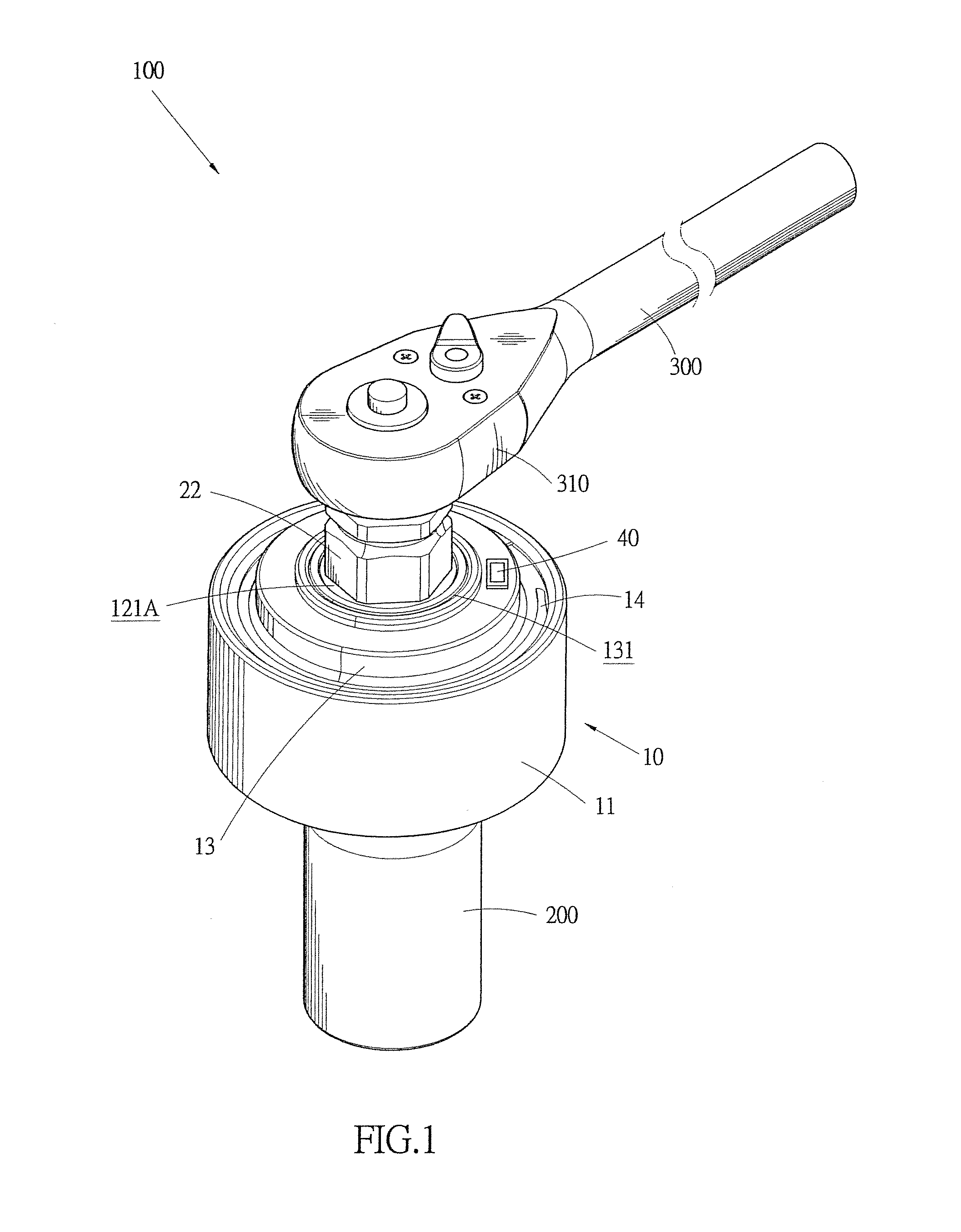
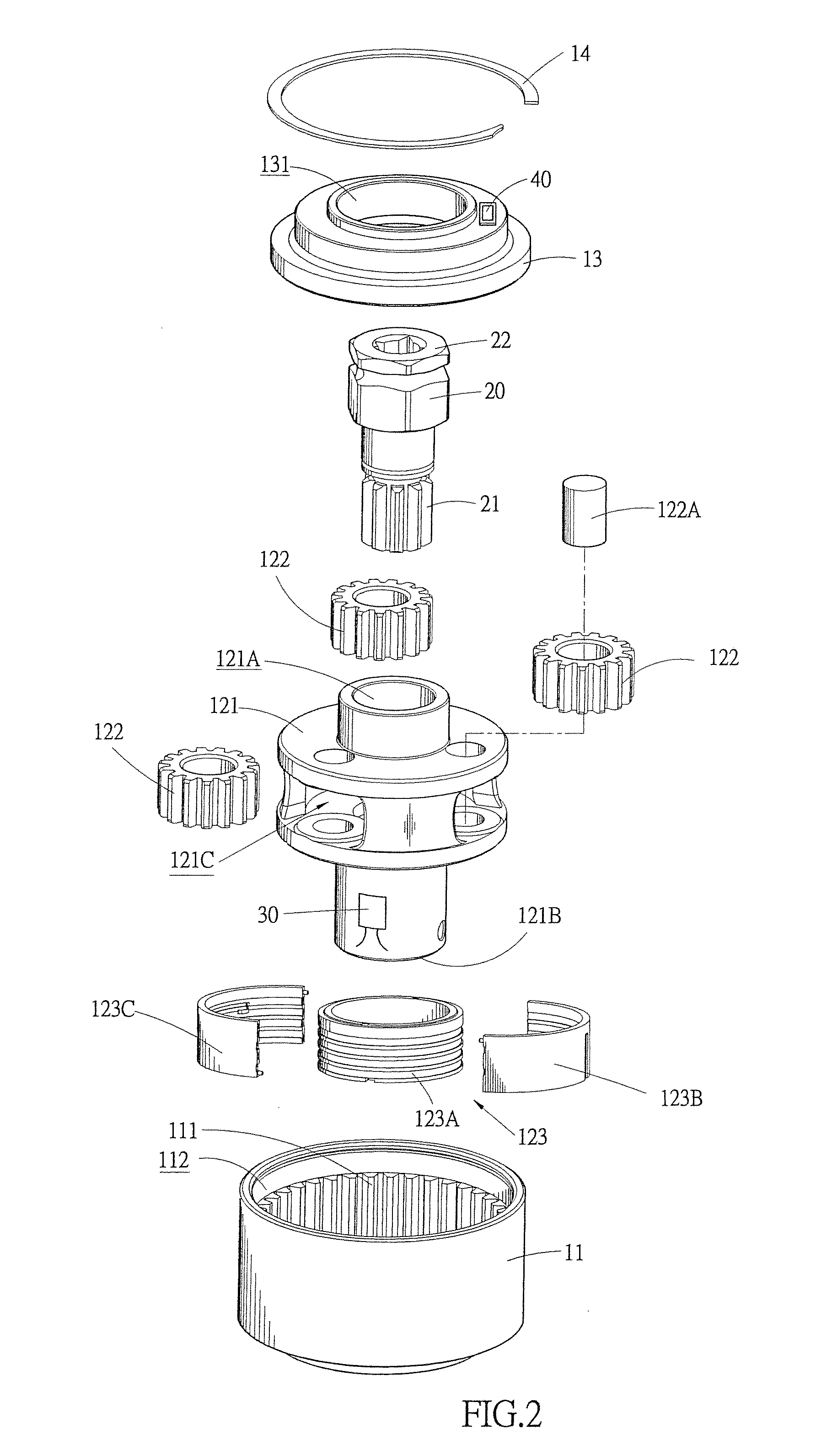
[0021]With reference to the drawings and in particular to FIGS. 1-4, a torque multiplier constructed in accordance with the present invention is shown at 100. The torque multiplier 100 comprises a main body 10, which comprises a casing 11, a gear train 12, a shaft seat 13, and a C-shaped retention ring 14. The casing 11 has an internal circumferential surface forming a plurality of teeth 111, and the casing 12 encloses and defines a chamber 112.

[0022]The gear train 12 is not limited to any specific form and includes, in an example of the present invention, a rotatable disk 121, a plurality of gears 122, and at least one signal pick-up device 123. The rotatable disk 121 is completely received in the chamber 112 of the casing 11. The rotatable disk 121 has an upper end forming a torque input port 121A and a lower end forming a torque output shaft 121B. The torque output shaft 121B is hollow and function's to couple to a tool piece 200, which is not limited to any specific form and may...

second embodiment

[0035]Referring to FIGS. 5-8, a torque multiplier constructed in accordance with the present invention is shown, and is also designated with reference numeral 100 for simplicity. The casing 11 of the main body 10 is provided externally with a connection bar 113. An assisting arm 114 has an end forming a connection opening 114A that is fit to the connection bar 113 and an opposite end forming an assisting board 114B. The assisting board 114B is positionable on a surface of a component 510 of an article 500 to be tightened (see FIG. 7). The articles 500 to be tightened and the component 510 thereof are not limited to any specific forms and in an embodiment of the present invention, a tire is taken as an example of the article 500 to be tightened, and the component 510 is a nut. In this arrangement, a torque device 300 that is combined with the torque multiplier 100 of the present invention can be supported by the assisting arm is the operation thereof so that the torque multiplier 100...

third embodiment

[0037]Referring to FIGS. 9 and 10, a torque multiplier constructed in accordance with the present invention is shown. The shaft seat 13 forms a plurality of through holes 132. The top of the casing 11 forms a plurality of threaded holes 115 that correspond to the through holes 132 and receive bolts 116 to extend therethrough and engage therewith to secure the shaft seat 13 and the casing 11 together. The central bore 131 of the shaft seat 13 receives a bearing 133 therein. The gear train 12 comprises a primary gear train 125 and a secondary gear train 124, a first ring gear 126, a second ring gear 127, a bearing 128, a C-shaped retention ring 129, and a signal pick-up device 123. The secondary gear train 124 comprises a rotatable disk 124A and a plurality of gears 124B. The rotatable disk 124A forms therein a receiving compartment 124A′ that receives the gears 124B to each rotatably connected between upper and lower ends of the rotatable disk 124A. The upper and lower ends of the ro...


PUM


Abstract

A torque multiplier includes a main body, a torque input shaft, at least one torque sensor, an angle sensor, and an information transmission circuit. The main body contains therein at least one gear train. The gear train has upper and lower ends respectively forming a torque input port and a torque output shaft. The torque output shaft is coupleable with a tool piece, such as a socket. The torque input shaft has an end fit into the torque input port and an opposite end coupleable with a torque device, such as a hand tool, an electrical tool, or a pneumatic tool. The torque device applies a torque input to the torque input shaft that in turn rotates the gear train to provide a multiplied torque output to the torque output shaft. The torque sensor is mounted to a surface of the torque output shaft of the gear train of the main body to detect the torque value of the torque output shaft and provide a torque value signal. At least one angle sensor mounted to the main body detects a horizontal angle of the main body and the torque output shaft and provides an angle value signal. The information transmission circuit is arranged inside the main body to transmit, in a wired or wireless fashion, the torque value signal and the angle value signal to at least one electronic device for storage, display or use.

Description

BACKGROUND OF THE INVENTION[0001]1. Field of the Invention[0002]The present invention relates to a torque multiplier, and in particular to a torque multiplier that is applicable to torque output of various torque devices and performs detection and transmission of torque value and horizontal angle value in wired or wireless manner to an external electronic device for displaying and application of these values.[0003]2. The Related Arts[0004]A torque multiplier is commonly used in applications where torque based operations are performed in order to provide multiplied torque output through a gear train included in the torque multiplier for power or torque saving for the conventional torque devices, such as hand tools, electrical tools, and pneumatic tools. In a regular operation of a conventional torque multiplier, a threaded fastener, such as a nut, used in a machine or a mechanical part, must be tightened or loosened by following predetermined operation processes with preset levels of...

Claims


Application Information

Patent Timeline
Patent Type & Authority Patents(United States)
IPC IPC(8): B25B13/00B25B29/00B25B21/00B25B17/00B23B23/00B25B13/50
CPCB25B17/02B25B23/0078B25B23/14B25B23/1425
Inventor CHEN, CHIANG KAO
Owner LEGEND LIFESTYLE PRODS CORP
Why Eureka
Try Eureka