Electric circuit protection system and method for protecting an electric circuit

a protection system and electric circuit technology, applied in emergency protection arrangements for limiting excess voltage/current, electrical devices, and arrangements responsive to excess current, etc., can solve the problems of significant increases in the energy of current that is transmitted to the load, damage to the load that is powered by current, and relatively sensitive electronic components

Active Publication Date: 2013-11-19
GENERAL ELECTRIC CO
View PDF17 Cites 26 Cited by
  • Summary
  • Abstract
  • Description
  • Claims
  • Application Information

AI Technical Summary

Problems solved by technology

The current may temporarily and abruptly increase, or “spike,” which can cause significant increases in the energy of the current that is transmitted to the load.
Overcurrent events can damage the load that is powered by the current.
For example, the load may include relatively sensitive electronic components that are damaged or destroyed by overcurrents of significantly high energy.
Alternatively, the overcurrent events can risk injuring operators of the load.
One problem with relying on the energy threshold value of a fuse to protect the load and / or operators of the load is that the energy threshold value may be dependent on external factors, such as the temperature and / or age of the fuse.
The fuse may unnecessarily blow at overcurrents having energies that are low enough for the load and / or operators of the load to safely withstand.
Additionally, the fuse may be located in a relatively difficult location to reach.
As a result, in order to replace the blown fuse, significant downtime of the circuit and load may be required.
One problem with some known contactors is that the contactors have a response time or delay between receiving instructions to open the circuit and actually opening the circuit.
This current has energy referred to as “let-through fault energy.” The let-through fault energy can degrade fuses that are coupled with the circuit and / or damage or injure the load and operators of the load.

Method used


Image

  • Electric circuit protection system and method for protecting an electric circuit
  • Electric circuit protection system and method for protecting an electric circuit
  • Electric circuit protection system and method for protecting an electric circuit

Examples


Embodiment Construction

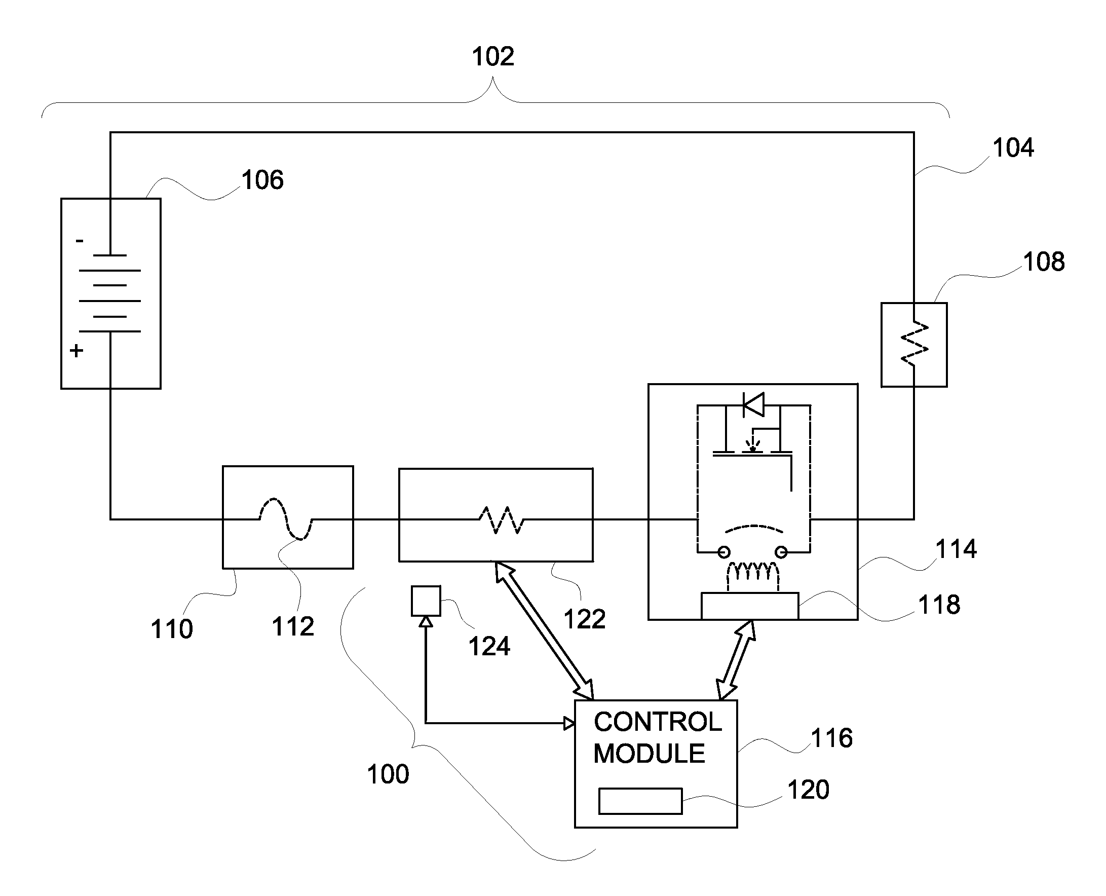
[0014]One or more embodiments of the subject matter described herein relate to over current protection devices for electric circuits. FIG. 1 is a circuit diagram of an electric circuit protection system 100 coupled with an electric circuit 102 in accordance with one embodiment. The electric circuit 102 includes a conductive bus 104, such as a wire or other conductive body, that electrically couples a power source 106 with an electric load 108. The circuit 102 also includes a fuse assembly 110 and a controlled switch 114 disposed between the power source 106 and the electric load 108. The controlled switch 114 generically shows both an example of an electronic switch, such as a MOSFET, IGBT, MCT, SSR, BJT, SCR or triac, and a mechanical switch, such as a contactor or relay. The protection system 100 monitors one or more degradation factors related to the fuse assembly 110 in order to determine when the switch 114 should be opened in order to prevent blowing the fuse assembly 110 and / ...


PUM


Abstract

An electric circuit protection system includes a control module and a circuit sensor communicatively coupled with the control module. The control module is communicatively coupled with a switch that is joined with a circuit having a power source and a fuse. The control module is configured to monitor a degradation factor related to an energy threshold value of the fuse and direct the switch to open the circuit to prevent the power source from supplying current through the fuse. The circuit sensor is configured to measure an energy parameter of the current supplied by the power source through the circuit or that is demanded by a load from the power source. The control module is configured to direct the switch to open the circuit based on the energy threshold value and the energy parameter.

Description

BACKGROUND[0001]One or more embodiments of the subject matter described herein relate to over current protection devices for electric circuits.[0002]Known electric circuits include a power source that delivers alternating or direct current to an electric load through one or more conductive busses. The current may temporarily and abruptly increase, or “spike,” which can cause significant increases in the energy of the current that is transmitted to the load. The variances or spikes in the current may be referred to as an overcurrent, or an overcurrent event. Overcurrent events can damage the load that is powered by the current. For example, the load may include relatively sensitive electronic components that are damaged or destroyed by overcurrents of significantly high energy. Alternatively, the overcurrent events can risk injuring operators of the load.[0003]In order to protect loads from such overcurrents, some known circuits include overcurrent protection devices, such as fuses a...

Claims


Application Information

Patent Timeline
Patent Type & Authority Patents(United States)
IPC IPC(8): H02H3/08
CPCH02H5/04
Inventor JEZIERSKI, CHESTER STANLEYWIEGMAN, HERMANHOU, SUYUDJOKANOVIC, BOJANBOGDAN, JR., DAVID
Owner GENERAL ELECTRIC CO
Why Eureka
Try Eureka