Solar panel assembly attachment apparatus

a technology for solar panels and attachment devices, which is applied in the direction of heat collector mounting/support, lighting and heating apparatus, and connection contact material, etc. it can solve the problems of difficult installation on site, time-consuming and labor-intensive conventional lug and threaded fastener devices, and inconvenient use, etc., to reduce assembly costs, improve quality, and reduce manufacturing and installation costs.

Active Publication Date: 2013-11-26
A RAYMOND & CO
View PDF99 Cites 75 Cited by
  • Summary
  • Abstract
  • Description
  • Claims
  • Application Information

AI Technical Summary

Benefits of technology

[0006]The present invention is advantageous over traditional devices. For example, the clip of the present apparatus is inexpensive to manufacture and install. Furthermore, the present grounding clip is suitable for pre-assembly to the frame offsite or at a manufacturing plant, thereby improving quality and reducing assembly cost. Moreover, the present grounding clip allows for simple linear frame attachment and simple linear strut attachment free of extraneous loose parts such as threaded fasteners, nuts and brackets. The multiple clamp and barb configurations of the present apparatus also advantageously increase the electrical grounding continuity and reliability to the solar panel frame as compared to conventional devices. Additional advantages and features of the present invention will become apparent from the following description and appended claims.BRIEF DESCRIPTION OF THE DRAWINGS
[0016]Referring now to FIGS. 3-7, grounding clip 17 includes a pair of spaced apart clamps 51 and 53, an upper bridge 55 and a mounting section 57. Each clamp 51 and 53 has a generally C-shape defined between an upper wall 61, a lower wall 63 and a back wall 65, thereby creating an openly accessible receptacle 67 therebetween. Furthermore, a lead-in wall 69 upwardly and outwardly angles away from upper wall 61 to ease insertion of a flat lateral flange 81 of frame 15 therein during assembly. A pair of pointed barbs 83 internally project from each upper section of clamps 51 and 53. Each barb 83 cuts into and gouges the adjacent surface of flange 81 to scrape off the anodized coating on the aluminum frame 15 thereat. This provides multiple satisfactory electrical grounding paths between the base material of the frame and the clip. This can be achieved by the simple linear insertion of the clamps of the clip onto the flange of the frame without the need for rotation or a threaded attachment. Furthermore, a stiffening bead 85 is centrally provided on each upper wall 61 and back wall 65 to control the desired flexure of clamps 51 and 53.
[0018]A longitudinally elongated stiffening bead 125 is also provided along a lower diagonally angled segment of each wing 103. Moreover, tapered ends 107 of mounting section 101 abut against each other in a offset crossing manner so as to deter buckling or collapsing of the mounting section during installation or removal of the clip from the strut. Each end of clip 17 includes a downwardly stepped locating tab 131. This tab fits within channel 39 of strut 13 to deter undesired rotation of clip 17 relative to the strut when installed.
[0019]It is also noteworthy that the spaced apart and multiple clamps 51 and 53 of grounding clip 17 provide a longer and more secure attachment geometry to frame 15 while also providing four redundant electrical grounding paths. In other words, the clamp spacing relative to the wings deters inadvertent knocking off of the clip from the frame during strut attachment. In one construction, clip 17 electrically grounds frame 15 to strut 13 or, in another construction, may alternately have a hole for receiving a screwed-on eyelet or other separate wire along bridge 55 to thereby ground frame 15 to a separately wired circuit.
[0020]When fully installed, the solar panel hides a majority of the clip. This feature advantageously deters theft of the solar panel by making it less clear to a casual observer that compression together of the wings will allow detachment of the clip from the strut. Clip 17 is preferably stamped from a Magni coated spring steel, but alternately may be made from stainless steel.

Problems solved by technology

These devices, however, solely provide frame retention, and are time consuming and complex to install on a job site, such as on top of a windy roof, which thereby incurs significant labor expense and effort.
This patent highlights many of the disadvantages of this lug and threaded fastener approach.
Furthermore, this conventional lug and threaded fastener device is time consuming and difficult to install on site and is not easily suited for pre-assembly.

Method used


Image

  • Solar panel assembly attachment apparatus
  • Solar panel assembly attachment apparatus
  • Solar panel assembly attachment apparatus

Examples


Embodiment Construction

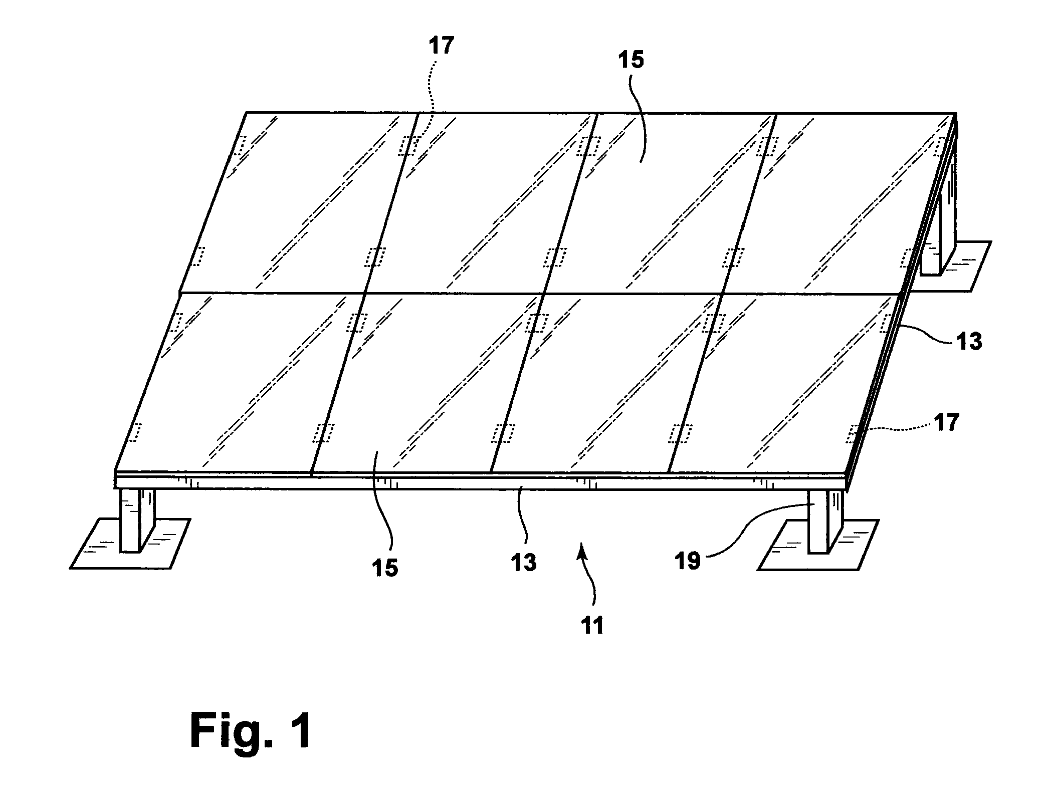
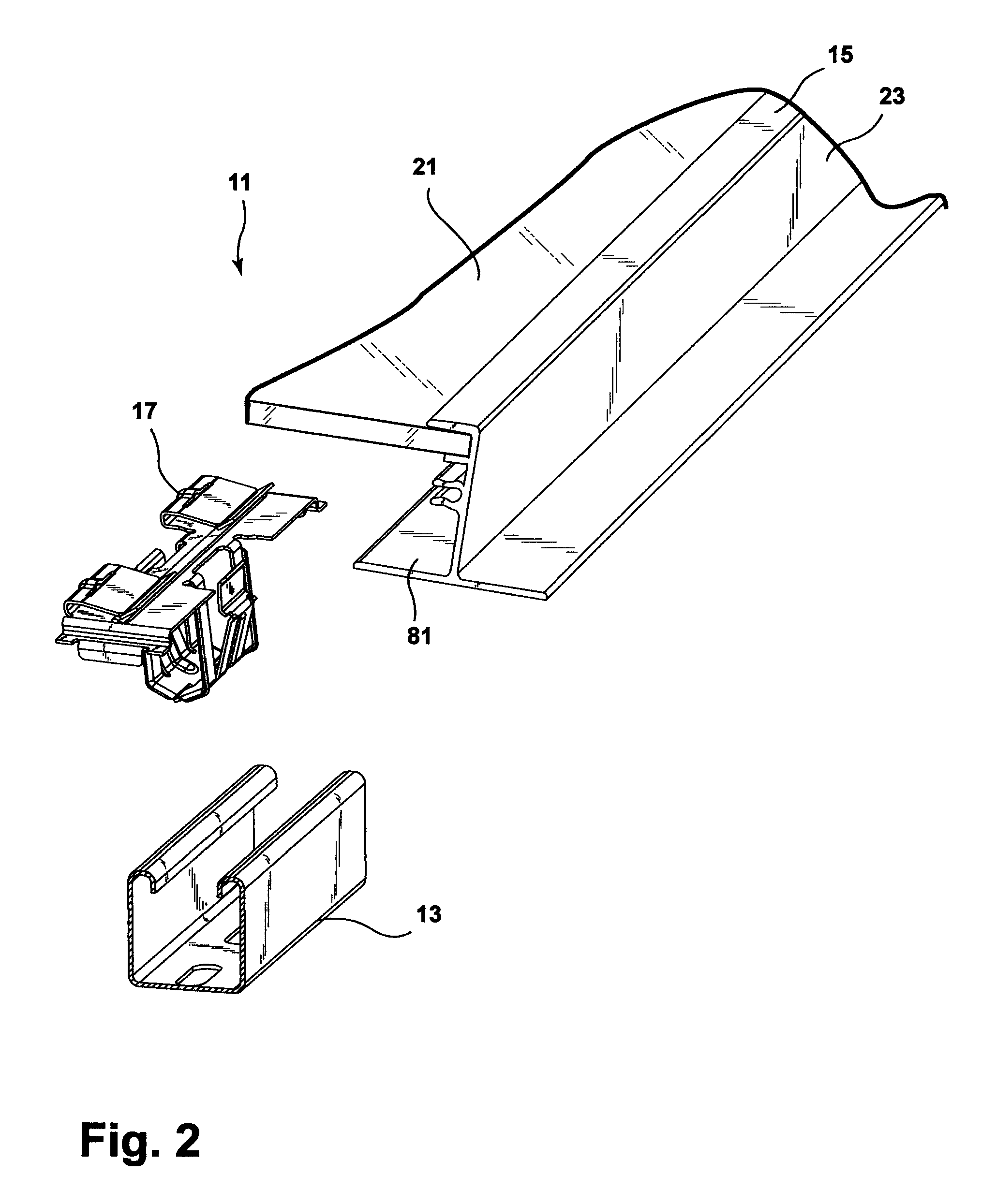
[0014]Referring to FIGS. 1-4, a solar panel assembly attachment apparatus 11 includes elongated and rigid struts 13, solar panel modules or assemblies 15, and grounding clips 17. Struts 13 are either mounted to vertical legs 19 attached to land, or are bolted onto a roof clamp or other structure on the top or side of a building. Each solar panel assembly 15 includes a glass photovoltaic panel 21 and a metallic frame 23.

[0015]Strut 13 has a uniform generally U-cross-sectional shape defined by upstanding side walls 31 joined by a bottom wall 33. A reverse-turned wall 35 extends from a top end of each side wall 31 and terminates in a downwardly directed edge 37. An elongated slot or channel 39 is defined between walls 35. Optional mounting holes 41 are provided in bottom wall 33 to allow for bolt or other building attachment. Strut 13 is preferably stamped or rolled from aluminum or steel.

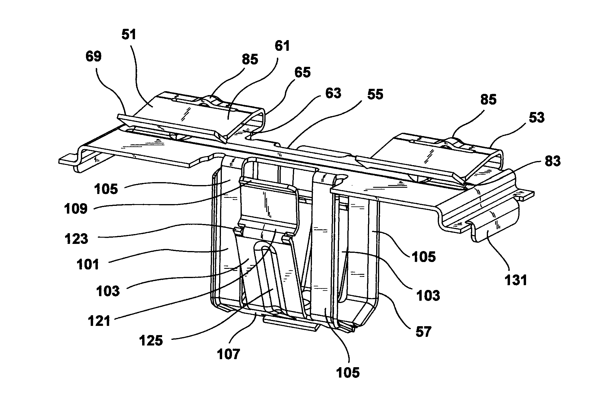
[0016]Referring now to FIGS. 3-7, grounding clip 17 includes a pair of spaced apart clamps 51 and ...


PUM

PropertyMeasurementUnit
electrically conductiveaaaaaaaaaa
widthaaaaaaaaaa
T-shapeaaaaaaaaaa

Abstract

A solar panel assembly attachment apparatus is provided. In another aspect, a single piece and entirely metallic grounding clip is employed. A further aspect includes a clip or fastener which provides both frame grounding and a frame-to-strut attachment. In still another aspect, a grounding clip having barbs is linearly slid onto a solar panel frame and the clip additionally includes one or more flexible wings which are removably snap-fit into a slot of an elongated and rigid strut.

Description

BACKGROUND AND SUMMARY[0001]The present invention relates generally to a solar panel assembly attachment apparatus and more particularly to a grounding clip which attaches a solar panel frame to a strut.[0002]Traditionally, peripheral mounting frames holding solar or photovoltaic panels are mounted to a supporting structure on a building roof or on the land through use of threaded fasteners and multi-piece brackets. Exemplary traditional devices are disclosed in U.S. Pat. No. 7,758,011 entitled “Adjustable Mounting Assembly for Standing Seam Panels” which issued to Haddock on Jul. 20, 2010, and U.S. Pat. No. 6,105,317 entitled “Mounting System for Installing an Array of Solar Battery Modules of a Panel-Like Configuration on a Roof” which issued to Tomiuchi et al. on Aug. 22, 2000. These patents are incorporated by reference herein. These devices, however, solely provide frame retention, and are time consuming and complex to install on a job site, such as on top of a windy roof, whic...

Claims


Application Information

Patent Timeline
Patent Type & Authority Patents(United States)
IPC IPC(8): E04D13/18
CPCF24J2/5256H01R4/26F24J2/5254H02S20/24H02S20/10H01R4/64Y02E10/50Y10T29/49355Y02E10/47Y10T29/49208F24J2002/522F24S25/632F24S25/634F24S2025/804Y02B10/10
Inventor KILGORE, DORIAN J.TELLER, WILLIAMEVANGELISTA, ELIO G.MCCULLAH, JUSTINWAGNER, THOMASDUPONT, LUCVANBOXEL, JAMES
Owner A RAYMOND & CO
Why Eureka
Try Eureka