Resonator with a fluid cavity therein

a quartz-based resonator and fluid cavity technology, applied in the direction of fluid pressure measurement, fluid tightness measurement, specific gravity measurement, etc., can solve the problems of difficult alignment of tape and quartz resonators, difficult operation, and porous resonators which are not suitable for liquid isolation, etc., to achieve greater sensitivity

Active Publication Date: 2013-11-26
HRL LAB
View PDF199 Cites 11 Cited by
  • Summary
  • Abstract
  • Description
  • Claims
  • Application Information

AI Technical Summary

Problems solved by technology

Chemically etching inverted mesas has been used to produce higher frequency resonators, but this usually produces etch pits in the quartz that can result in a porous resonator which is not suitable for liquid isolation.
In addition, the alignment of tape and the quartz resonators can be difficult and unreliable thereby causing operational variations.
Current UHF quartz MEMS resonators fabricated for integration with electronics (see U.S. Pat. No. 7,237,315) can not be used in commercial low cost sensor cartridges since one metal electrode can not be isolated in a liquid from the other electrode and electrical connections can not be made outside the liquid environment.
However, as stated above, handling and cracking issues usually dictate that the lapped and polished thicknesses are of the order of 100 microns, and chemically etching deep inverted mesas produces etch pits which significantly reduce the yield and can result in a porous resonator.

Method used


Image

  • Resonator with a fluid cavity therein
  • Resonator with a fluid cavity therein
  • Resonator with a fluid cavity therein

Examples


Embodiment Construction

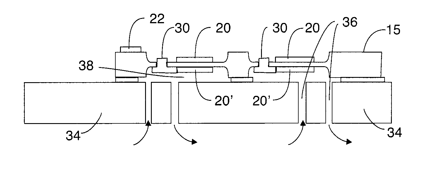
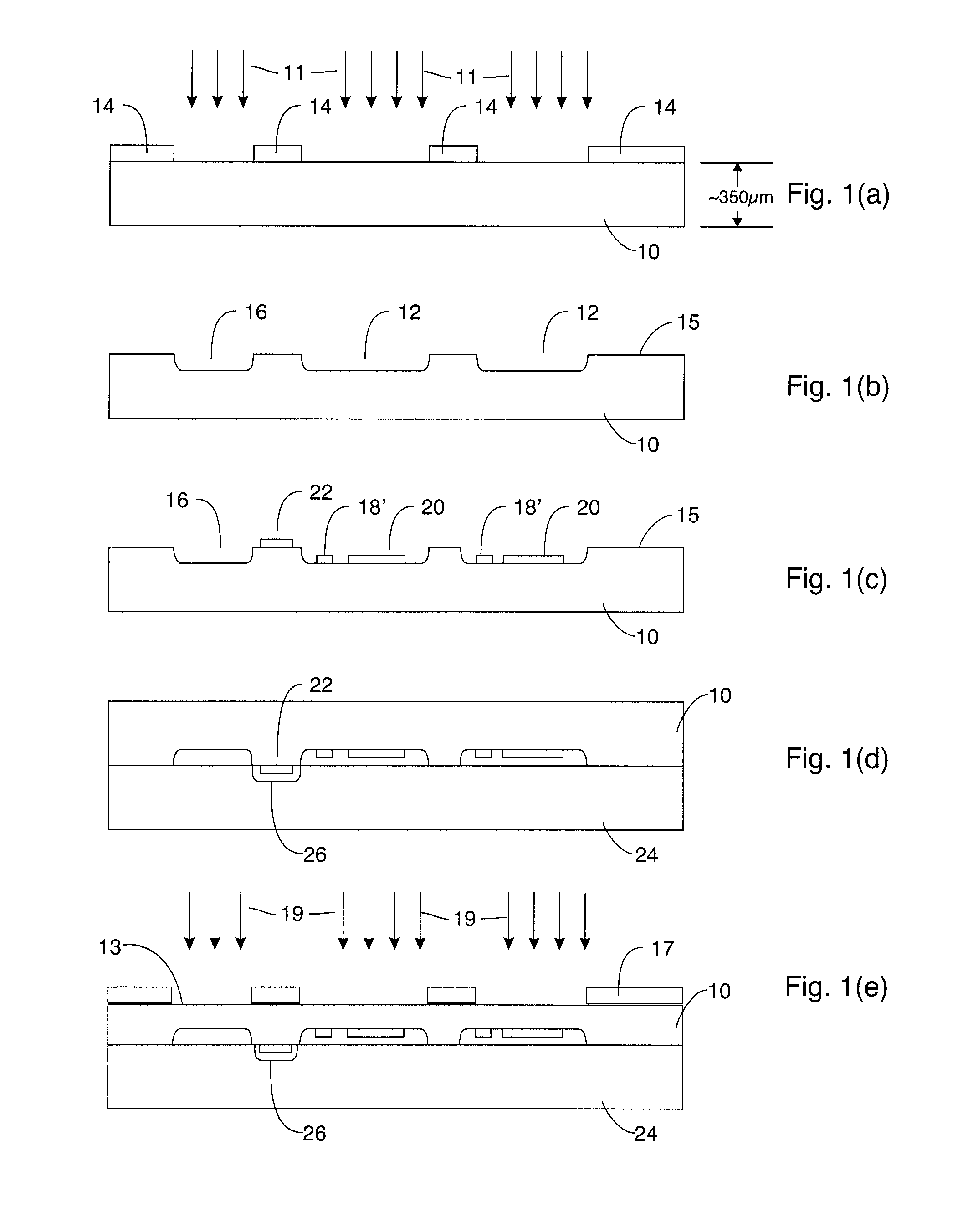
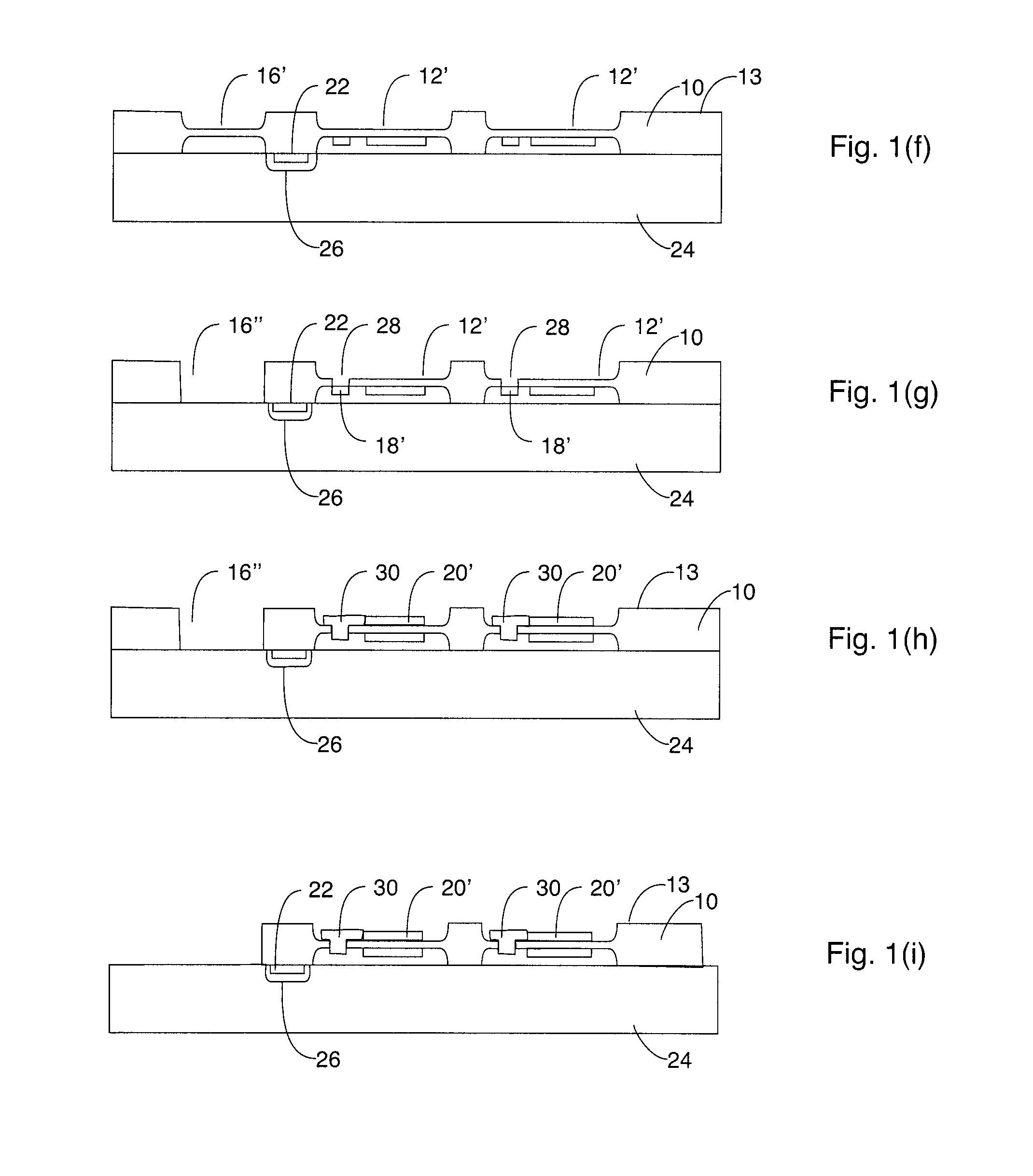
[0015]FIGS. 1(a)-1(l) depict, in a series of side elevational views, steps which may be used to make the sensor described herein. These elevation views are taken along a section line 1-1 depicted in FIG. 2.

[0016]The formation of the disclosed sensor starts with a piezoelectric quartz wafer 10 preferably 3″˜ 4″ in diameter, AT-cut, with a thickness of preferably about 350 microns. As shown in FIG. 1(a), a mask 14 in combination with a dry plasma etch 11 (to prevent the formation of etch pits), are preferably used to form inverted mesas 12 (see FIG. 1(b)) etched in a top or first surface of wafer 10. Mask 14 is preferably formed of a thick resist or metal such as Ni or Al. In this connection, a solid layer of Ni or Al is may be put down and then a conventional photo-mask may be used to etch the Ni or Al in order to make mask 14 out of that metal. The preferred approach is to electroplate Ni onto a resist mold to form mask 14. This dry plasma etch 11 through mask 14 is optional, but is...


PUM

PropertyMeasurementUnit
frequencyaaaaaaaaaa
thickaaaaaaaaaa
frequencyaaaaaaaaaa

Abstract

A quartz resonator flow cell has a piezoelectric quartz wafer with an electrode, pads, and interconnects disposed on a first side thereof. The piezoelectric quartz wafer has a second electrode disposed on a second side thereof, the second electrode opposing the first electrode. A substrate is provided having fluid ports therein and the piezoelectric quartz wafer is mounted to the substrate such that the second side thereof faces the substrate with a cavity being formed between the substrate and the wafer. The fluid ports in the substrate are aligned with the electrode on the second side of the piezoelectric quartz wafer which is in contact with the cavity.

Description

CROSS REFERENCE TO RELATED APPLICATIONS[0001]This application is a divisional of U.S. application Ser. No. 12 / 575,634 entitled “High Frequency Quartz-based Resonators and Methods of Making Same” filed on Oct. 8, 2009, the contents of which are hereby incorporated by reference.[0002]Published PCT Application WO 2006 / 103439 entitled “Cartridge for a Fluid Sample Analyzer” and U.S. Pat. No. 7,237,315, entitled “Method for Fabricating a Resonator” are hereby incorporated herein by this reference.TECHNICAL FIELD[0003]This application relates to high frequency quartz-based resonators, which may be used in biological analysis applications at high frequencies such as VHF and / or UHF frequencies, and methods of making same.BACKGROUND[0004]Small biological detectors using quartz mass sensing currently are commercially implemented using low frequency (˜10 MHz) quartz resonators on macro-size substrates mounted on plastic disposable cartridges for biological sample exposure and electrical activa...

Claims


Application Information

Patent Timeline
Patent Type & Authority Patents(United States)
IPC IPC(8): H01L41/053H01L41/107H01L41/113H01L41/047G01P3/26G01L7/00
CPCH04R17/00Y10T29/49165Y10T29/42Y10T29/49401
Inventor KUBENA, RANDALL L.HSU, TSUNG-YUAN
Owner HRL LAB
Why Eureka
Try Eureka