
Three-phase LED power supply

a three-phase led power supply and led lamp technology, applied in the direction of electric variable regulation, process and machine control, instruments, etc., can solve the problems of unsatisfactory three-phase a.c. power matching of led-based lamps, complex and costly circuitry, and undesirable electrical work at the distribution panel

Active Publication Date: 2013-11-26
GE LIGHTING SOLUTIONS LLC
View PDF15 Cites 40 Cited by
  • Summary
  • Abstract
  • Description
  • Claims
  • Application Information

AI Technical Summary

Benefits of technology

The patent describes an apparatus and method for converting three-phase AC power into regulated DC power using a three-phase rectifier and a d.c.-to-d.c. converter. The apparatus also includes a power distribution bus to deliver the DC power to LED based lamps located at a distance from the rectifier. The technical effect of this invention is to provide a more efficient and reliable way to power LED based lamps, which can be used in a variety of applications such as lighting fixtures.

Problems solved by technology

Thus, LED-based lamps are generally not well-matched to three-phase a.c. power.
These approaches employ complex and costly circuitry.
As a result, the electrical connection of an LED-based lamp typically requires performing substantial electrical work at the three-phase a.c. power distribution panel, such as installing one or more dedicated phase-to-ground or phase-to-phase power taps.
Such extensive electrical work at the distribution panel is undesirable and can introduce substantial safety concerns.
This approach adversely impacts maintenance.
However, this approach has the disadvantage of requiring low voltage, high current d.c. electrical power to be conducted from ground level to the elevated location of the lamp, which increases “I2R” resistive power losses.

Method used


Image

  • Three-phase LED power supply
  • Three-phase LED power supply
  • Three-phase LED power supply

Examples


Embodiment Construction

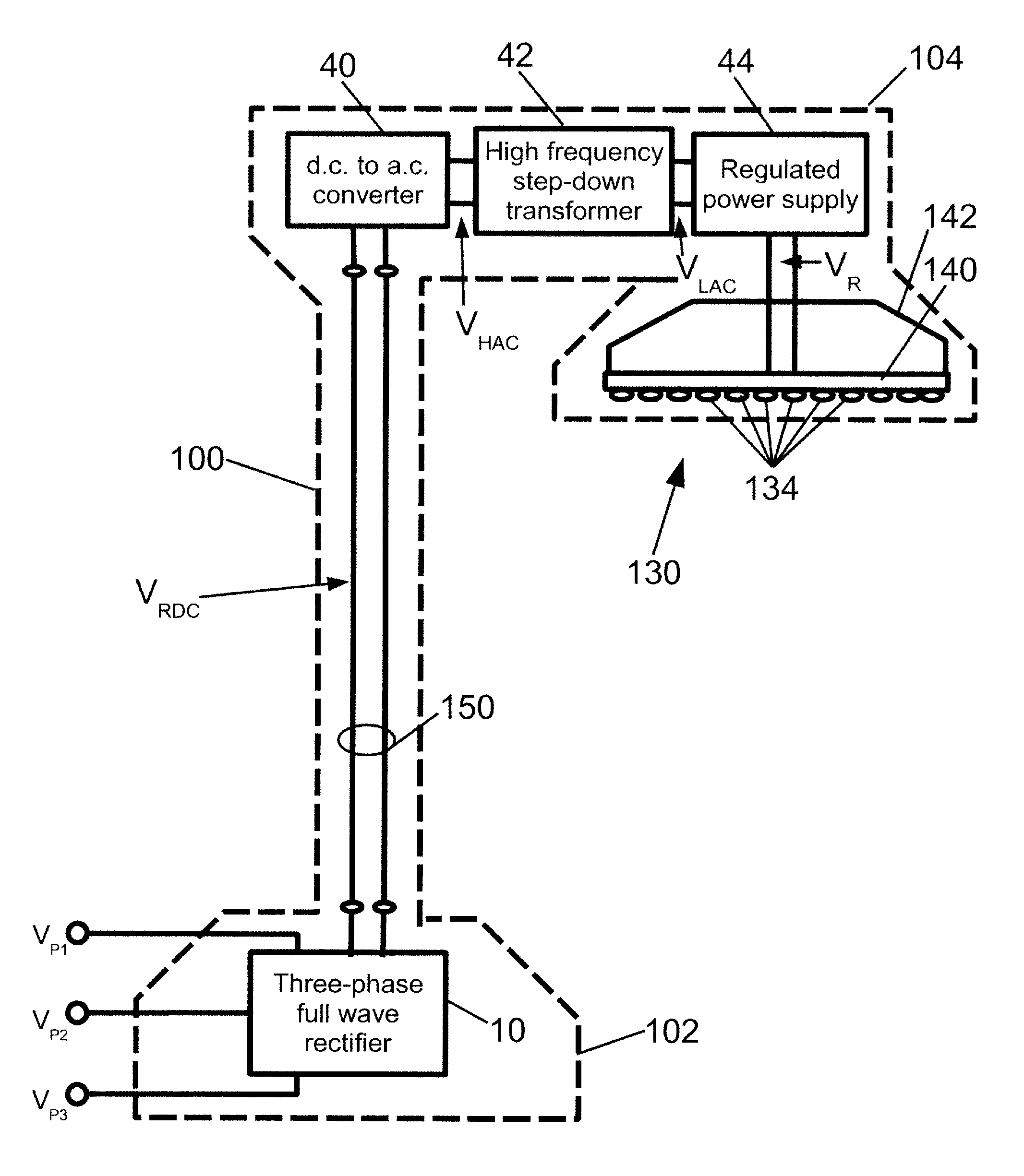
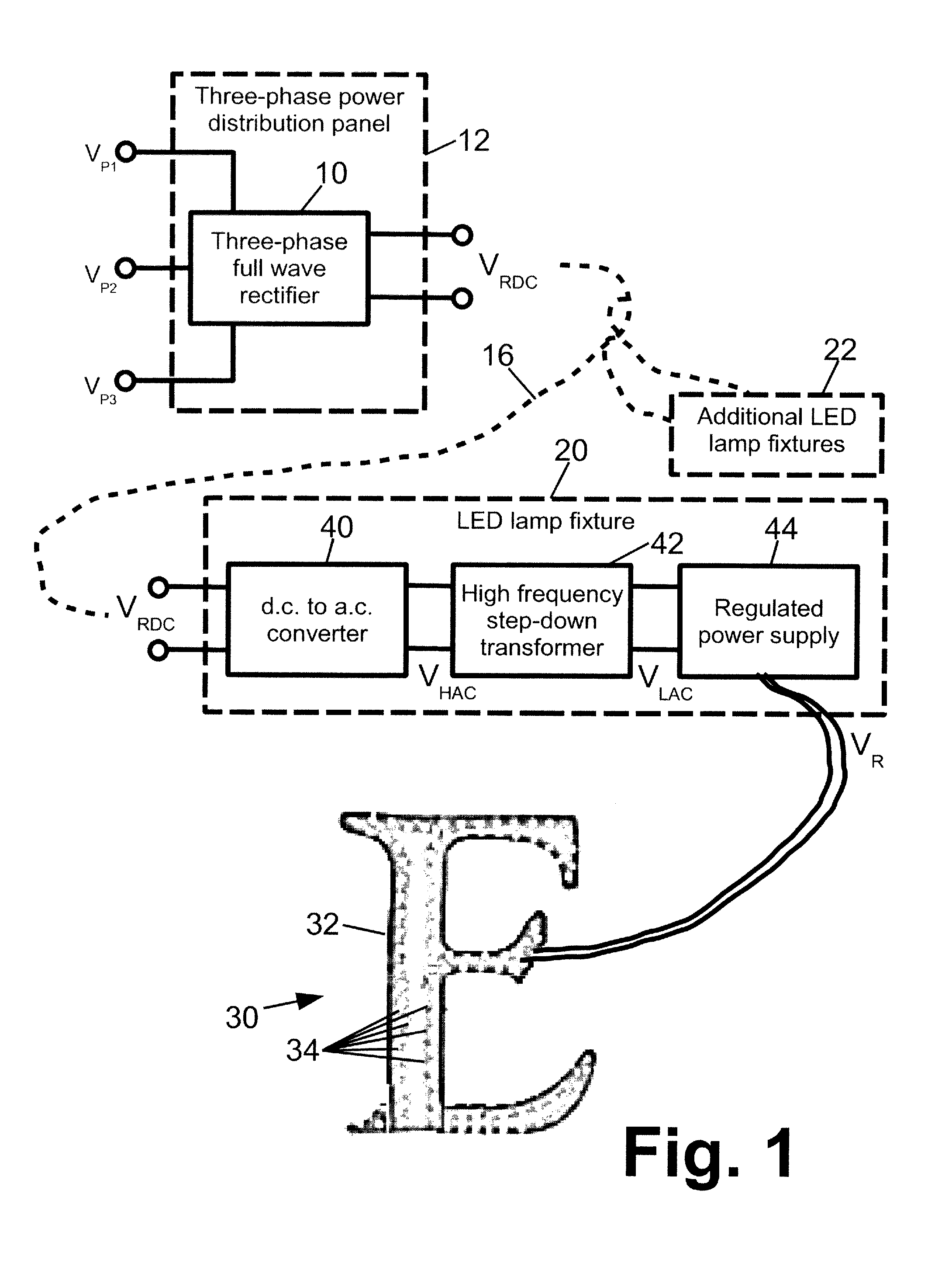
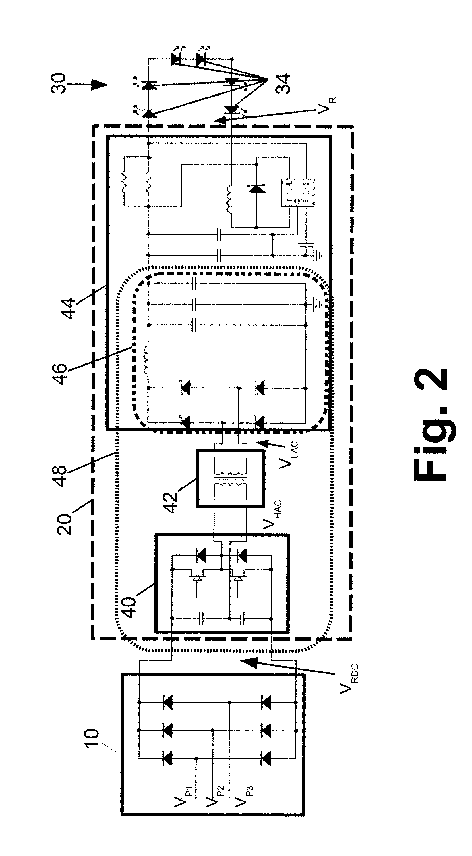
[0018]With reference to FIGS. 1-5, an apparatus includes a three-phase full-wave rectifier 10 which in the illustrated embodiment of FIG. 1 is disposed in a three-phase power distribution panel 12. The three-phase full-wave rectifier 10 receives three-phase a.c. power including phases VP1, VP2, VP3 and outputs a ripple d.c. voltage VRDC. The phases VP1, VP2, VP3 may, for example, be phase-to-neutral or phase-to-phase a.c. voltages of a wye (“Y”) connected three-phase power configuration or of a delta (“Δ”) connected three-phase power configuration. As shown in FIG. 5, the three phases VP1, VP2, VP3 are input via corresponding three terminals TP1, TP2, TP3 of a terminal block 14 configured for installation in the three-phase a.c. power distribution panel 12, while the ripple d.c. voltage VRDC is output across terminals To+, To−. The illustrated terminal block 14 also includes an optional neutral path having an input terminal TN connected with the electrical neutral or ground of the t...


PUM


Abstract

A three phase rectifier rectifies received three phase a.c. power to generate a ripple d.e. voltage. A power distribution bus conveys distribution power comprising the ripple d.c. voltage or an a.c. voltage derived therefrom to a location of an LED based lamp that is distal from the three phase rectifier. Additional circuitry disposed with the LED based lamp drives the LED based lamp using the distribution power.

Description

BACKGROUND[0001]The following relates to the illumination arts, lighting arts, electrical power arts, and related arts.[0002]Light emitting diode (LED)-based lamps are employed in diverse outdoor lighting and illumination systems, such as traffic lighting, overhead (e.g., post-mounted) lamps, billboard and other commercial illuminated signage, and so forth. These lighting or illumination systems are sometimes in the context of commercial or industrial applications, such as commercial signage, parking lot illumination for retail centers, malls, supermarkets, and the like, or so forth.[0003]In commercial and industrial settings, the available electrical power is typically three-phase a.c. power, such as 120 / 208 V or 277 / 480 V three-phase power as is typical in commercial or industrial settings in the United States, or 220 / 380 V three phase power in China, or so forth. The three-phase power is typically high voltage (for example, over 100 volts per phase). For high operating efficiency...

Claims


Application Information

Patent Timeline
Patent Type & Authority Patents(United States)
IPC IPC(8): H05B37/00H02M7/00
CPCH05B33/0815H05B45/375H05B45/39
Inventor WANG, JIANZHAO, HONG
Owner GE LIGHTING SOLUTIONS LLC
Learn More