
Systems and methods for prediction of objective visual acuity based on wavefront measurements

a wavefront measurement and objective visual acuity technology, applied in the field of optical system analysis, can solve problems such as not being representative of the quality of eye optics

Active Publication Date: 2013-12-03
AMO MFG USA INC
View PDF51 Cites 8 Cited by
  • Summary
  • Abstract
  • Description
  • Claims
  • Application Information

AI Technical Summary

Benefits of technology

The present invention provides a method and system for accurately estimating the visual acuity of an eye. This is done by measuring the visual distortion caused by optical aberrations of the eye, constructing an acuity model, and using it to determine the estimated visual acuity of the eye. The estimated acuity accurately correlates to the actual acuity of the eye, which can help in predicting and diagnosing optical acuity issues. The kit includes instructions and a system for doing so.

Problems solved by technology

The test results from such methods, however, can be subjective in nature as they involve the human brain's interpretation of vision, and therefore may not be representative of the quality of the eye's optics.

Method used


Image

  • Systems and methods for prediction of objective visual acuity based on wavefront measurements
  • Systems and methods for prediction of objective visual acuity based on wavefront measurements
  • Systems and methods for prediction of objective visual acuity based on wavefront measurements

Examples


Embodiment Construction

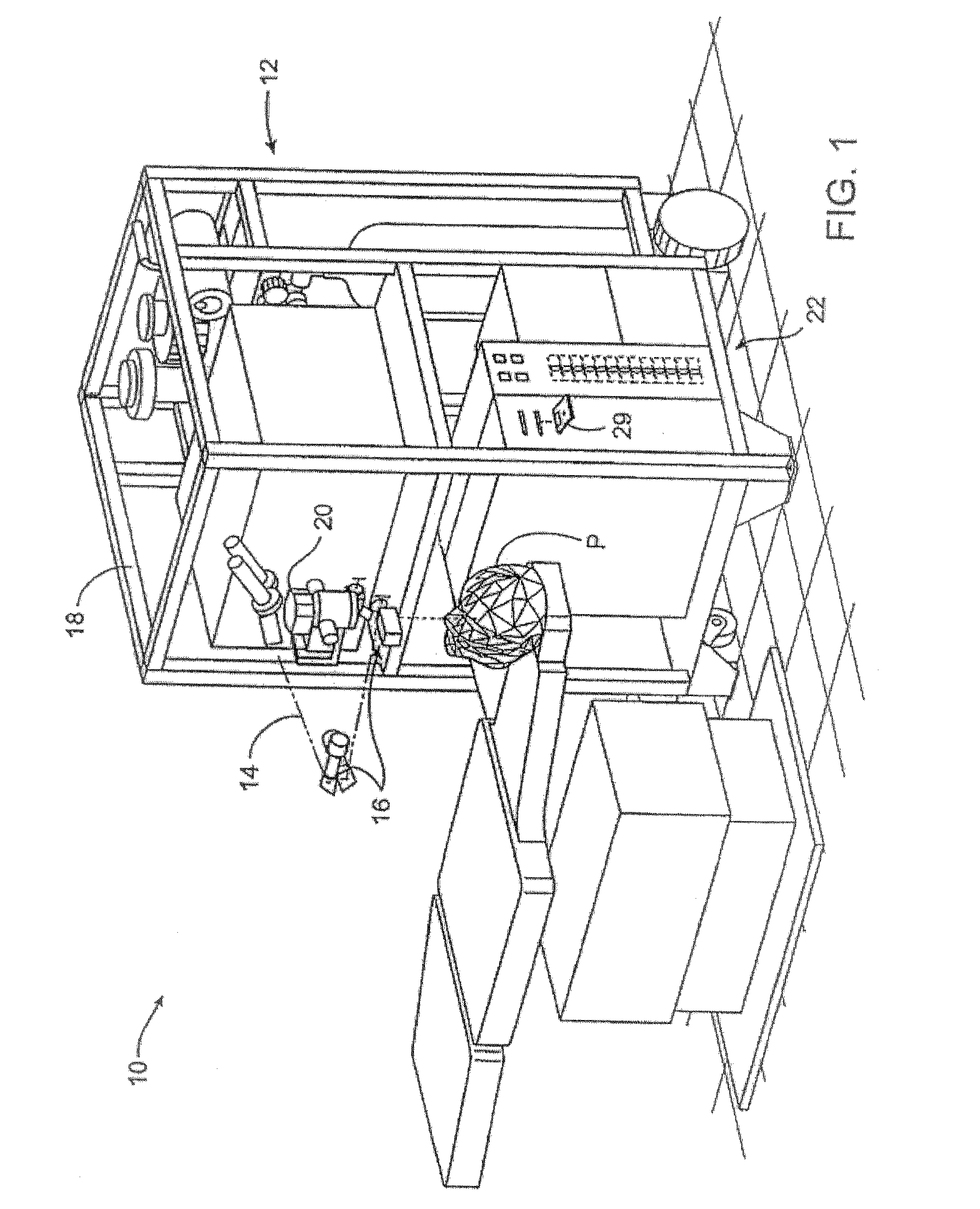
[0076]Turning now to the drawings, FIG. 1 illustrates a laser eye surgery system 10 of the present invention, including a laser 12 that produces a laser beam 14. Laser 12 is optically coupled to laser delivery optics 16, which directs laser beam 14 to an eye E of patient P. A delivery optics support structure (not shown here for clarity) extends from a frame 18 supporting laser 12. A microscope 20 is mounted on the delivery optics support structure, the microscope often being used to image a cornea of eye E.

[0077]Laser 12 generally comprises an excimer laser, ideally comprising an argon-fluorine laser producing pulses of laser light having a wavelength of approximately 193 nm. Laser 12 will preferably be designed to provide a feedback stabilized fluence at the patient's eye, delivered via delivery optics 16. The present invention may also be useful with alternative sources of ultraviolet or infrared radiation, particularly those adapted to controllably ablate the corneal tissue with...


PUM


Abstract

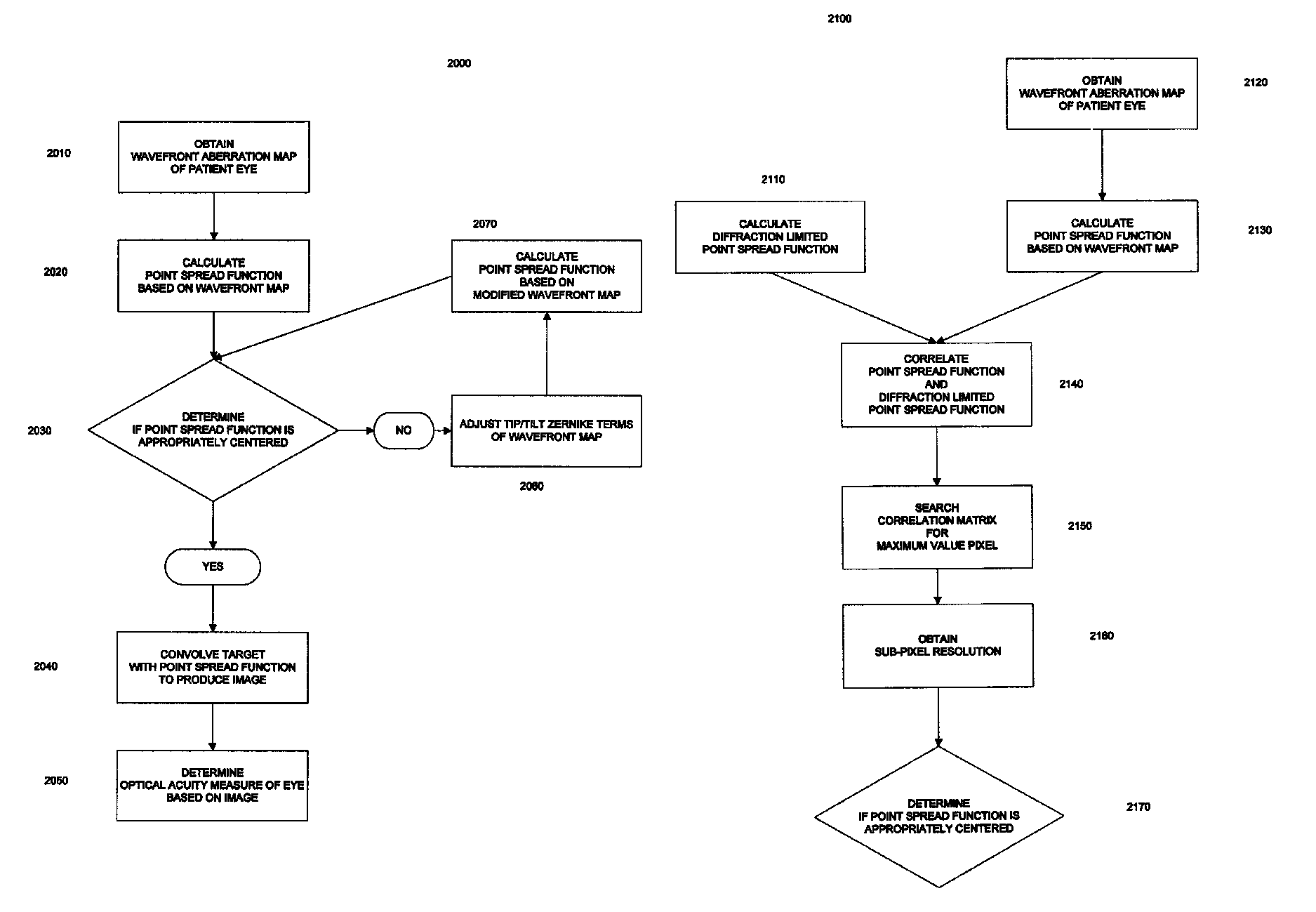
Methods, devices, and systems for predicting an optical acuity measure of an optical system of an eye. An optical acuity measure can be predicted by determining a point spread function based on a wavefront measurement of an eye, convolving a resolution target with the point spread function to produce an image, and predicting the optical acuity measure of the optical system of the eye based on the image.

Description

CROSS-REFERENCES TO RELATED APPLICATIONS[0001]This application is a continuation-in-part of U.S. patent Application Ser. No. 12 / 649,575, filed Dec. 30, 2009, now U. S. Pat. No. 7,997,731, which is a division of U.S. patent application Ser. No. 12 / 013,763, filed Jan. 14, 2008, now U. S. Pat. No. 7,699,470, which is a division of U.S. patent application Ser. No. 10 / 871,344, filed Jun. 18, 2004, now U. S. Pat. No. 7,338,165, which claims priority from U.S. Provisional Patent Application No. 60 / 480,237, filed Jun. 20, 2003. The entire disclosure of each of these applications is incorporated herein by reference for all purposes.BACKGROUND OF THE INVENTION[0002]This invention relates to optical system analysis, and in particular provides methods and systems for evaluating an optical acuity measure of an individual's eye.[0003]The visual acuity of the eye can be affected by many factors. For example, visual acuity can be affected by objective factors such as the optical characteristics of ...

Claims


Application Information

Patent Timeline
Patent Type & Authority Patents(United States)
IPC IPC(8): A61B3/10
CPCA61F9/00806A61F2009/00848A61F2009/00855A61F2009/00872A61F2009/0088
Inventor DAI, GUANGMING
Owner AMO MFG USA INC
Learn More