Cutting tool having pocket bottom with base and inclined surfaces

a cutting tool and pocket technology, applied in the field of cutting tools, can solve the problems of screw damage, pocket bottom and side surfaces not being structured to provide any support, and the cutting insert mounted on the milling cutting tool for performing a high-speed process receiving a considerable amount of cutting load, etc., and achieves the effect of convenient manufacturing of the cutting insert and the main body of the tool

Inactive Publication Date: 2013-12-03
TAEGUTEC
View PDF25 Cites 8 Cited by
  • Summary
  • Abstract
  • Description
  • Claims
  • Application Information

AI Technical Summary

Benefits of technology

[0010]The present invention is designed to solve the above problems associated with the conventional cutting tools. It is an object of the present invention to provide a cutting tool, which is configured to be simple in structure, while being capable of reliably securing a cutting insert to the pocket part of the main body of the tool.
[0013]According to the present invention, the second inclined surface, which is provided to the lower surface of the cutting insert, contacts the bottom surface of the pocket part on the surface, thereby providing a predetermined resistance against the cutting load outwardly applied from the main body. As such, the cutting insert can be reliably mounted onto the pocket part of the main body. In addition, the lower surface of the cutting insert and the bottom surface of the pocket part of the main body can be formed to have a simple configuration. Also, the number of surfaces where the cutting insert and the pocket part of the main body contact is minimized. This facilitates the manufacture of the cutting insert and the main body of the tool.
[0014]Moreover, the entire portion of the lower surface of the cutting insert is in the downwardly convex shape. This allows the cutting insert to receive a compressing force from the bottom surface of the pocket part without any tensioning force when the cutting insert is pressurized against the pocket part by a screw. Generally, a super alloy cutting insert, which is weak against the tensioning force but strong against the compressing force, is advantageous in terms of strength. Further, any damage to the cutting insert can be reduced with a predetermined opposing force to the cutting load outwardly applied to the cutting insert (the opposing force provided by the bottom surface of the pocket part) compared to the structure of convex projections provided to a portion of the planar lower surface according to the prior art.

Problems solved by technology

A cutting insert mounted on a milling cutting tool for performing a high-speed process generally receives a considerable amount of cutting load during a cutting process.
However, the bottom and side surfaces of the pocket part are not structured to provide any support to the cutting insert against the cutting load applied in the outward direction of the main body of the milling tool.
This allows said cutting load to be transferred directly to the cutting insert, eventually applying an excessive force onto a screw and possibly causing damage to the screw.
However, this inevitably increases manufacturing costs.
However, since it is difficult to polish the lower surface (55) due to its geometrical structure, the lower surface cannot be brought to a precise process.
This causes the lower surface (55) not to precisely contact the bottom surface of the pocket part, thus failing to stably secure the cutting insert.
Moreover, a super alloy cutting insert generally tends to be weak against a tensioning force but strong against a compressing force.
This can result in creating cracks around the concaves (60).
Accordingly, an excessive force may be applied to the screw during screw-fastening for securing the cutting insert to the bottom surface of the pocket part, which can damage the screw.
In addition, from the concaves of the pocket part, the projections receive a predetermined opposing force to the cutting load, wherein said force is applied in the outward direction of the main body of the tool, thus ultimately damaging the projections.

Method used


Image

  • Cutting tool having pocket bottom with base and inclined surfaces
  • Cutting tool having pocket bottom with base and inclined surfaces
  • Cutting tool having pocket bottom with base and inclined surfaces

Examples


Embodiment Construction

[0025]The present invention will now be described with reference to the accompanying drawings.

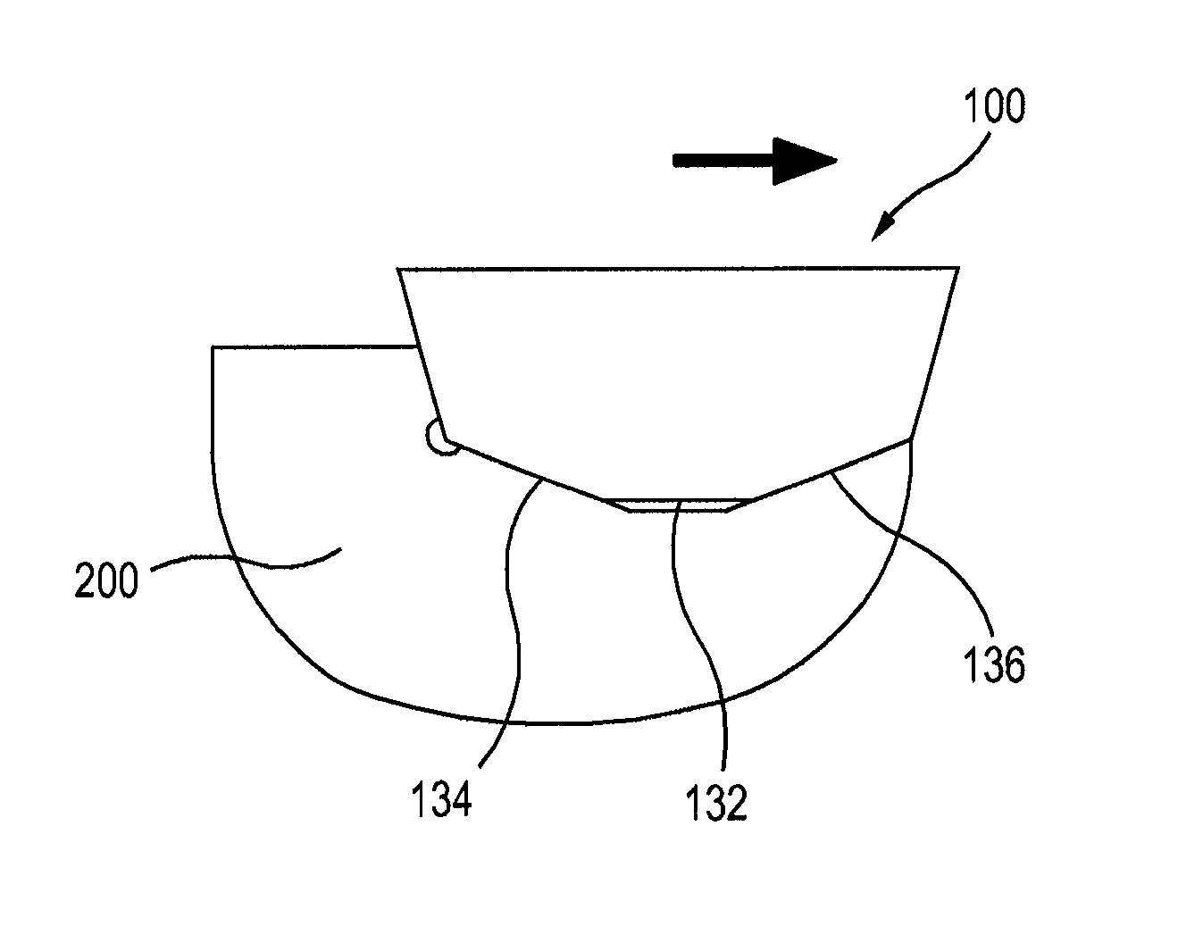
[0026]FIGS. 4 and 5 are perspective views respectively showing an upper portion and a lower portion of the cutting insert (100) according to an embodiment of the present invention. FIG. 6 is a lateral view of the cutting insert according to an embodiment of the present invention. FIG. 7 is a perspective view showing a pocket part of a main body of a cutting tool according to an embodiment of the present invention. With reference to FIGS. 4 and 5, the cutting insert (100) comprises an upper surface (110), a lower surface (130) and a side surface (120) connecting the upper surface (110) and the lower surface (130). The cutting insert (100) is provided with a through-hole (150), which passes through a center of the upper surface (110) and the lower surface (130). The cutting insert (100) is secured to a pocket part (300) of a main body (200) of a cutting tool by a screw (not shown), which is i...


PUM

PropertyMeasurementUnit
angleaaaaaaaaaa
angleaaaaaaaaaa
inclination anglesaaaaaaaaaa

Abstract

A cutting tool has a main body provided with a pocket part and a cutting insert. The pocket part includes at least one side wall and bottom surface which includes a pocket part base surface, a first pocket part inclined surface connected to an inner end of the base surface on an inside of the main body, and a second pocket part inclined surface connected to an outer end of the base surface on an outside of the main body. The cutting insert has an upper surface, a lower surface and side surfaces connecting the upper surface and the lower surface. The lower surface includes an insert base surface, first and second inclined surfaces inclined upwardly from first and second sides of the base surface, respectively. The cutting insert is seated in the pocket part such that the second inclined surface abuts the second pocket part inclined surface.

Description

RELATED APPLICATIONS[0001]This is a 35 USC 371 U.S. National Phase of International Application No. PCT / KR2008 / 007341, filed 11 Dec. 2008 and published in English as WO 2010 / 067910A1 on 17 Jun. 2010. The contents of the aforementioned application are incorporated by reference in their entirety.TECHNICAL FIELD[0002]The present invention generally relates to cutting tools, and more particularly to a milling cutting tool having a simple structure for performing a high-speed process to stably secure a cutting insert to a pocket part of a tool body.BACKGROUND ART[0003]A cutting insert mounted on a milling cutting tool for performing a high-speed process generally receives a considerable amount of cutting load during a cutting process. Accordingly, it is critical for the cutting insert used in the milling cutting tool to be reliably secured to the cutting tool body even under such a cutting load.[0004]Generally, the cutting tool body includes a pocket part wherein the cutting insert is mo...

Claims


Application Information

Patent Timeline
Patent Type & Authority Patents(United States)
IPC IPC(8): B23C5/22
CPCB23C5/2221B23C2200/161B23C2200/164B23C2210/168B23C2270/06B23C5/2213Y10T407/23Y10T407/2272Y10T407/1908Y10T407/2274Y10T407/1924
Inventor RYU, SU JIN
Owner TAEGUTEC
Why Eureka
Try Eureka