Assembly for a turbomachine

a turbomachine and assembly technology, applied in the field of turbomachines, can solve the problems of difficult sealing of one section difficult sealing of the turbomachine from the other, and the inability to prevent the gas leakage between the two parts, so as to prevent the relative displacement of the outer platform

Inactive Publication Date: 2013-12-03
ROLLS ROYCE PLC
View PDF10 Cites 4 Cited by
  • Summary
  • Abstract
  • Description
  • Claims
  • Application Information

AI Technical Summary

Benefits of technology

[0013]According to a first aspect of the present invention there is provided an assembly for a turbomachine comprising: a plurality of components which, in use, are assembled into a circumferentially extending annular array; each component having a radially outer platform, the outer platforms of the components forming a ring in the assembled array; wherein adjacent components interface at adjacent surfaces of their outer platforms, and the adjacent surfaces are angled away from the radial direction; wherein the outer platforms each comprise at least one lug which extends from the outer platform over a portion of the outer platform of an adjacent component, and in use substantially prevents relative radial displacement of the outer platform of the adjacent component. The components of the annular array may be contiguous.
[0020]Radial displacement of the radially superior surface may be prevented by means of the lug.

Problems solved by technology

The nozzle guide vane assembly is one of the most difficult areas of design because the vanes sustain the highest temperature in the engine and they must perform an efficient aerodynamic function on the hot gases which flow from the combustion chamber.
However, the operating conditions are such that components in the turbomachine exhibit different rates of expansion and contraction.
This brings about geometric relationships that change considerably during use, which makes it difficult to seal one section of the turbomachine from another to prevent leakage of gas between the two portions.
However, this puts large stresses into a relatively very thin component and the result is often that the strips are damaged and may even be torn in half.
However the method of U.S. Pat. No. 6,592,326 B2 does not deal with the differential in radial expansion experienced by guide vanes with a twisted aerofoil portion.
In such an arrangement, the differential in radial expansion creates a shear stress on the connection means and may lead to failure of the connection.
In addition, the process of connecting the components adds time to the manufacture of the guide vane and also in any subsequent disassembly and repair.

Method used


Image

  • Assembly for a turbomachine
  • Assembly for a turbomachine
  • Assembly for a turbomachine

Examples


Embodiment Construction

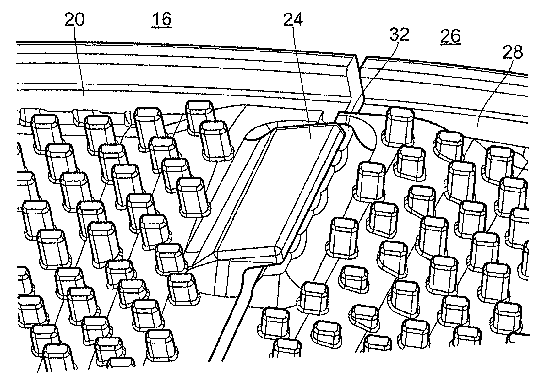
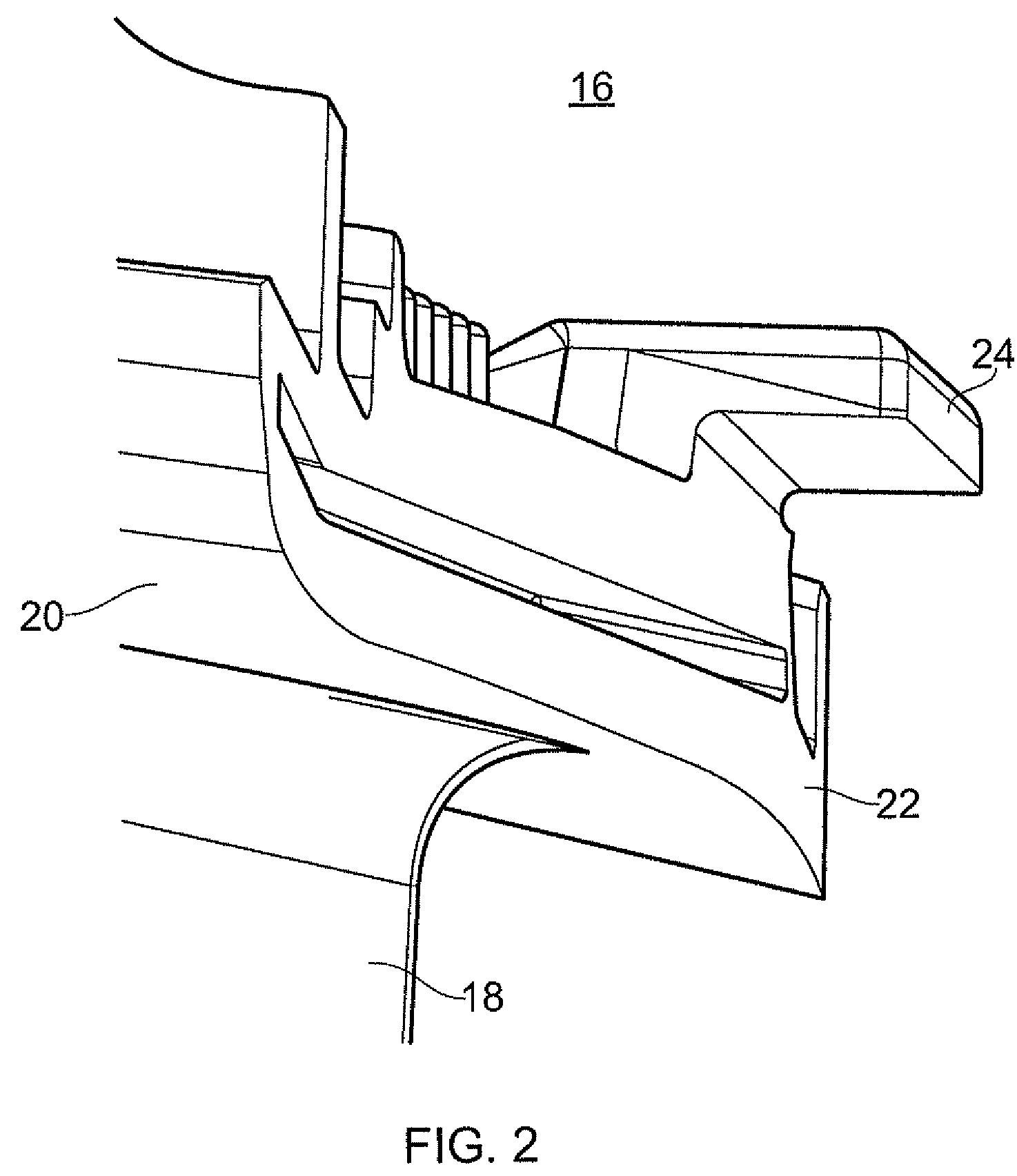
[0029]FIG. 2 illustrates a first component 16 of an assembly for a turbomachine in accordance with a first embodiment of the invention. As shown in FIG. 2, the component 16 comprises an aerofoil portion 18 and an inner platform (not shown) and an outer platform 20. The outer platform 20 has an angled surface 22 and at least one lug 24. The surface 22 is angled away from the radial direction. The lug 24 extends circumferentially from a portion of the outer platform 20 which is adjacent to the angled surface 22. The lug 24 is angled radially upward from the arc of the outer platform 20.

[0030]FIG. 3 illustrates a second component 26 of an assembly for a turbomachine in accordance with the first embodiment of the invention. As shown in FIG. 3, the second component 26 comprises an aerofoil portion (not shown) and an inner platform (not shown) and an outer platform 28. The outer platform 28 has an angled surface 30 and at least one pad 32. The surface 30 is offset from the radial directio...


PUM


Abstract

An assembly for a turbomachine comprising: a plurality of components (16, 26) which, in use, are assembled into a circumferentially extending annular array; each component having a radially outer platform (20, 28), the outer platforms (20, 28) of the components (16, 26) forming a ring in the assembled array; wherein adjacent components (16, 26) interface at adjacent surfaces (22, 30) of their outer platforms (20, 28); wherein the outer platforms (20, 28) each comprise at least one lug (24) which extends from the outer platform (20) over a portion of the outer platform (28) of an adjacent component (26), and in use prevents relative radial displacement of the outer platform (20, 28) of the adjacent component (16, 26).

Description

[0001]This invention relates to an assembly for a turbomachine.[0002]In particular the invention relates to an assembly for a turbomachine comprising a plurality of components, each having an outer platform, that are assembled into an array, the assembly being provided with a means of preventing relative radial displacement of the outer platforms.BACKGROUND[0003]A turbomachine, in particular a gas turbine engine, may comprise guide vanes in order to direct gas flows generated by the compressor and turbine stages of an engine. These vanes generally act between the stages of the engine and in particular the compressor stages to direct and guide the gas flow.[0004]The nozzle guide vane assembly is one of the most difficult areas of design because the vanes sustain the highest temperature in the engine and they must perform an efficient aerodynamic function on the hot gases which flow from the combustion chamber. The gases typically have an entry temperature between 850 and 1700° C. and...

Claims


Application Information

Patent Timeline
Patent Type & Authority Patents(United States)
IPC IPC(8): F03B1/04F01D9/04
CPCF01D5/225F01D9/041F05D2260/30F01D25/24F04D29/542
Inventor SPEED, KEITH R. F.DAVIS, PAUL A.
Owner ROLLS ROYCE PLC
Why Eureka
Try Eureka