Self-locking wire holder mounted in a housing of a charging connector

a charging connector and self-locking technology, which is applied in the direction of charging stations, transportation and packaging, and coupling device connections, etc., can solve the problems of wire breakage in the housing, wire damage, and the rotation of the wire holding member, so as to prevent the damage of the wir

Inactive Publication Date: 2013-12-03
SUMITOMO WIRING SYST LTD
View PDF13 Cites 15 Cited by
  • Summary
  • Abstract
  • Description
  • Claims
  • Application Information

AI Technical Summary

Benefits of technology

[0006]The invention relates to a wire holder to be mounted in a housing of a charging connector. The wire holder comprises a substantially box-shaped main body formed by assembling two half members with each other. The main body is prevented from moving in longitudinal and / or circumferential directions of a wire relative to the housing by the surface contact of the outer surface of the main body with the inner surface of the housing. At least one wire insertion hole is formed through the main body for holding the wire. The wire insertion hole is formed by cutting concave curves in edges of the half members and then assembling the half members so that edges with the concave curves abut and so that the concave curves oppose one another to form the wire insertion hole. The concave curves are dimensioned to tightly hold the wire without damaging the wire. The inability of the wire holder to rotate relative to the housing also prevents damage to the wire.
[0007]The half members may be identical components. Thus, the types of components can be reduced and component cost can be reduced.
[0008]The curved portions ensure a substantially uniform pressing force on the wire, thereby further preventing damage to the wire.
[0009]One or more escaping portions may be provided at the opposite ends of the curved portion and incline radially outward of the wire insertion hole. Accordingly, parts of the wire can enter the escaping portions to prevent the damage even if the curved portions are pressed excessively against the outer peripheral surface of the wire while assembling the half members.
[0010]Two wire insertion holes may be coaxially arranged while being spaced apart in the longitudinal direction of the wire. Accordingly, pressing forces on the wire in the respective wire insertion holes can be reduced since the wire is held in the wire insertion holes at two positions. Thus, damage to the wire is even less likely.

Problems solved by technology

Thus, the wire cannot be held when pulled with a strong force exceeding the frictional force and there is a possibility of wire breakage in the housing.
However, there is concern about damage to the wire and rotation of the wire holding member relative to the housing.

Method used


Image

  • Self-locking wire holder mounted in a housing of a charging connector
  • Self-locking wire holder mounted in a housing of a charging connector
  • Self-locking wire holder mounted in a housing of a charging connector

Examples


Embodiment Construction

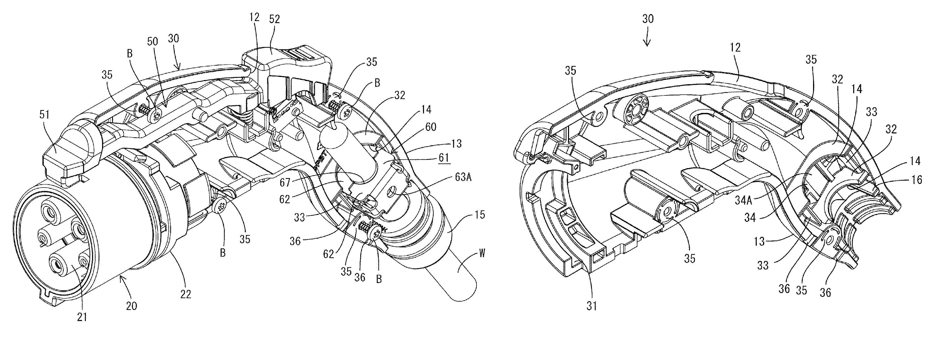
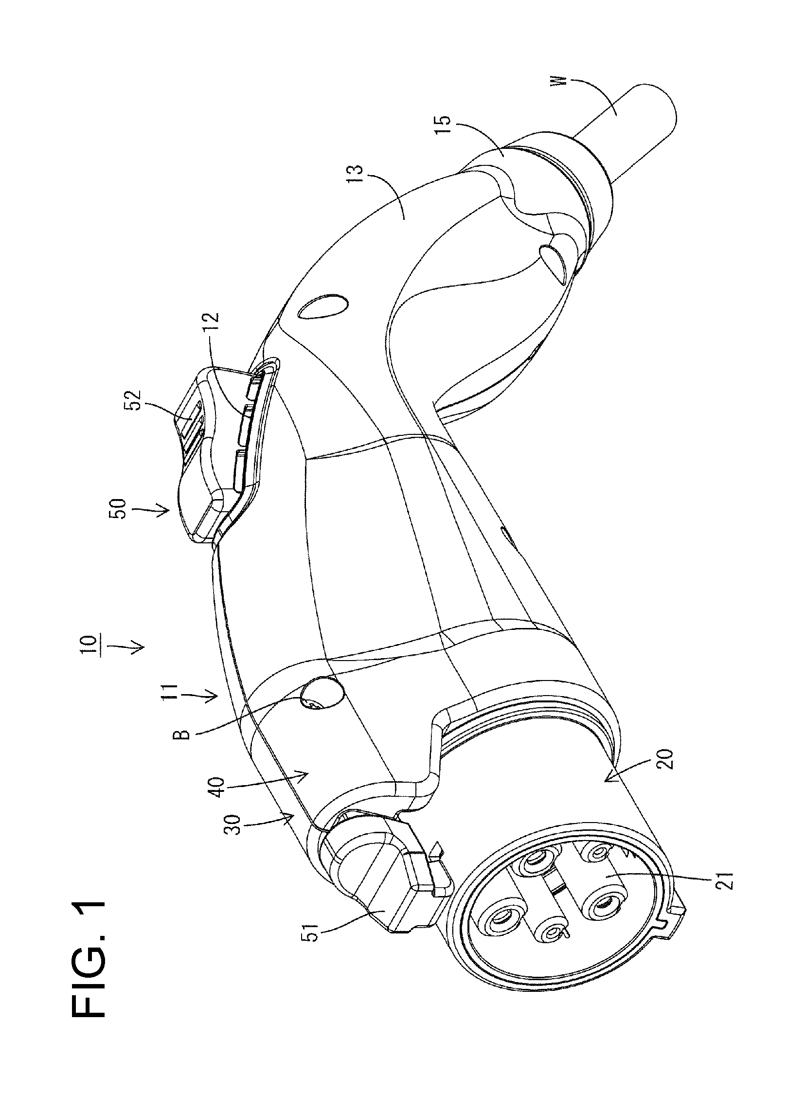
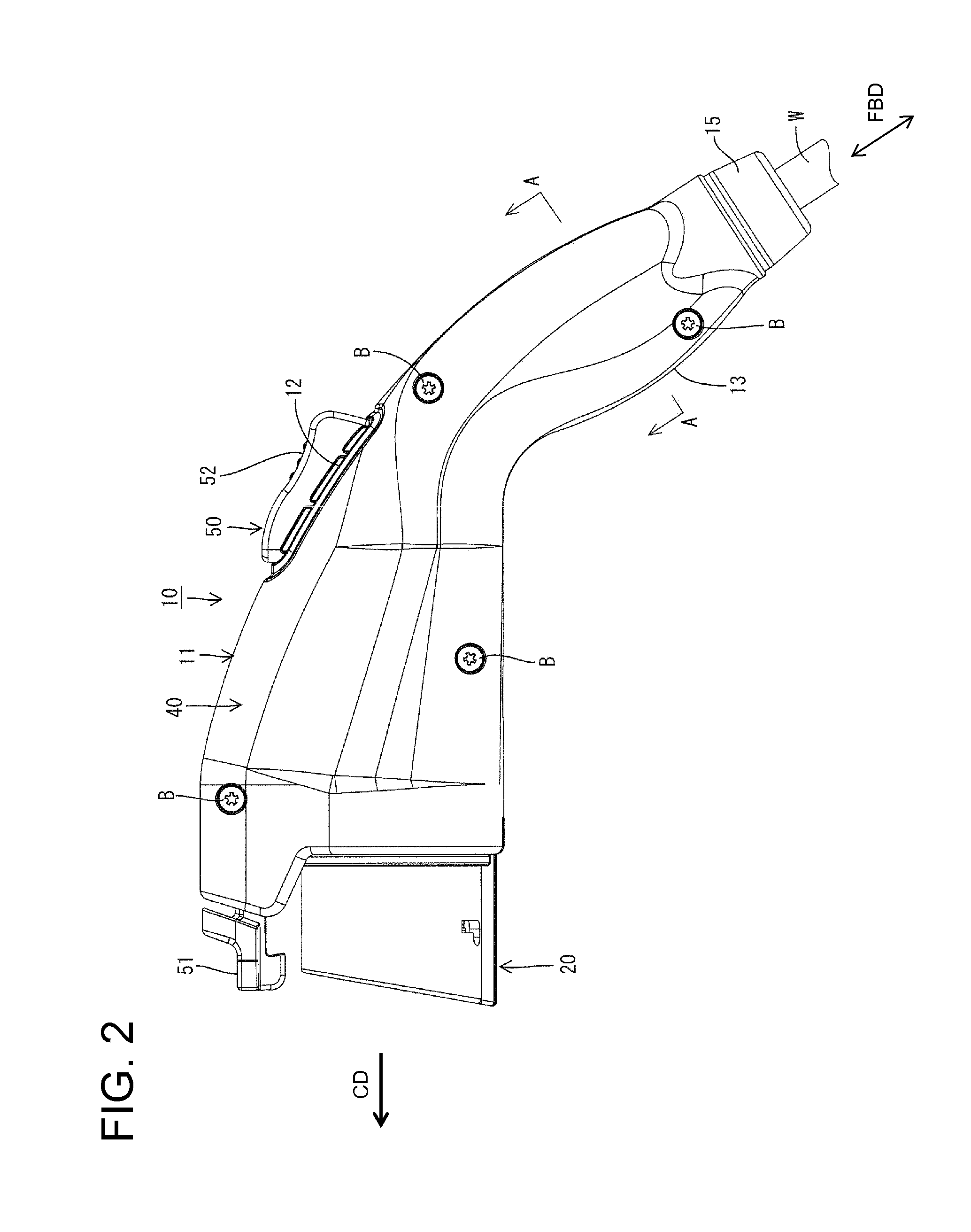
[0036]A charging connector in accordance with the invention is identified generally by the number 10 and includes a housing 11 having a pistol shape. The housing 11 comprises a front housing 20 connectable to a vehicle-side connector (not shown). A base housing 30 and a cover housing 40 hold the front housing 20 from left and right sides. Further, as shown in FIG. 2, the base housing 30 and the cover housing 40 are fixed to one another by bolts B. It should be understood that the base housing 30 and the cover housing 40 may be fixed to one another by clips, retainers, latches, or similar coupling members.

[0037]As shown in FIG. 3, at least one wire W is held in a clip 60 housed in a grip 13 of the housing 11. The clip 60 preferably is made of metal The grip 13 extends rearward from a release button 52 and is aligned obliquely down with respect to a connecting direction CD of the front housing 20 to the vehicle-side connector. Note that a longitudinal direction of the wire W is referr...


PUM


Abstract

A clip (60) is mounted in a housing (11) of a charging connector (10). The clip (60) includes a box-shaped main body (61) formed by assembling two half members (62, 62). The main body (61) is prevented from moving in longitudinal and circumferential directions of a wire (W) relative to the housing (11) by the surface contact of the outer surface of the main body (61) with the inner surface of the housing (11). Wire insertion holes (67) are formed in the main body (61) by assembling the half members (62, 62) so that pairs of curved portions (66, 66) face each other. The wire (W) is held in the main body (61) by being tightly held by the curved portions (66, 66).

Description

BACKGROUND OF THE INVENTION[0001]1. Field of the Invention[0002]The invention relates to a wire holder used for a charging connector and to a charging connector provided therewith.[0003]2. Description of the Related Art[0004]U.S. Pat. No. 6,602,090 discloses a wire holder for a charging connector with a housing and a wire holder retained in the housing. The wire holder is a cylindrical member made of rubber and is formed with wire insertion holes. Wires are inserted through the wire insertion holes. A tightening member, such as a crimp ring, then is tightened over the entire circumference of the wire holder to hold the wires. The wire holding of U.S. Pat. No. 6,602,090 holds the wires only by producing frictional forces between the inner peripheral surfaces of the wire insertion holes and the outer peripheral surfaces of the wires. Thus, the wire cannot be held when pulled with a strong force exceeding the frictional force and there is a possibility of wire breakage in the housing. ...

Claims


Application Information

Patent Timeline
Patent Type & Authority Patents(United States)
IPC IPC(8): H01R13/58
CPCB60L11/1818H01R13/5825Y02T90/14Y02T10/7005H01R2201/26B60L53/16Y02T10/70Y02T10/7072
Inventor OSAWA, KIYOSHIICHIO, TOSHIFUMI
Owner SUMITOMO WIRING SYST LTD
Why Eureka
Try Eureka