Operational line management of low pressure compressor in a turbofan engine

a technology of low pressure compressor and operating line, which is applied in the direction of instruments, vessel construction, optical radiation measurement, etc., can solve the problems of increasing the operating line of the low pressure compressor, reducing the stability margin, and reducing the physical nozzle exit area. , to achieve the effect of changing the nozzle exit area

Active Publication Date: 2013-12-10
RTX CORP
View PDF17 Cites 21 Cited by
  • Summary
  • Abstract
  • Description
  • Claims
  • Application Information

AI Technical Summary

Problems solved by technology

A limitation on the stability margin is an increase in low pressure compressor pressure ratio that occurs during throttle transients.
This results in a momentary increase in the low pressure compressor pressure ratio, which raises the low pressure compressor operating line and reduces stability margin until the high spool decelerates.
This can result in the low pressure compressor being operated at non-optimal performance conditions.

Method used


Image

  • Operational line management of low pressure compressor in a turbofan engine
  • Operational line management of low pressure compressor in a turbofan engine
  • Operational line management of low pressure compressor in a turbofan engine

Examples


Embodiment Construction

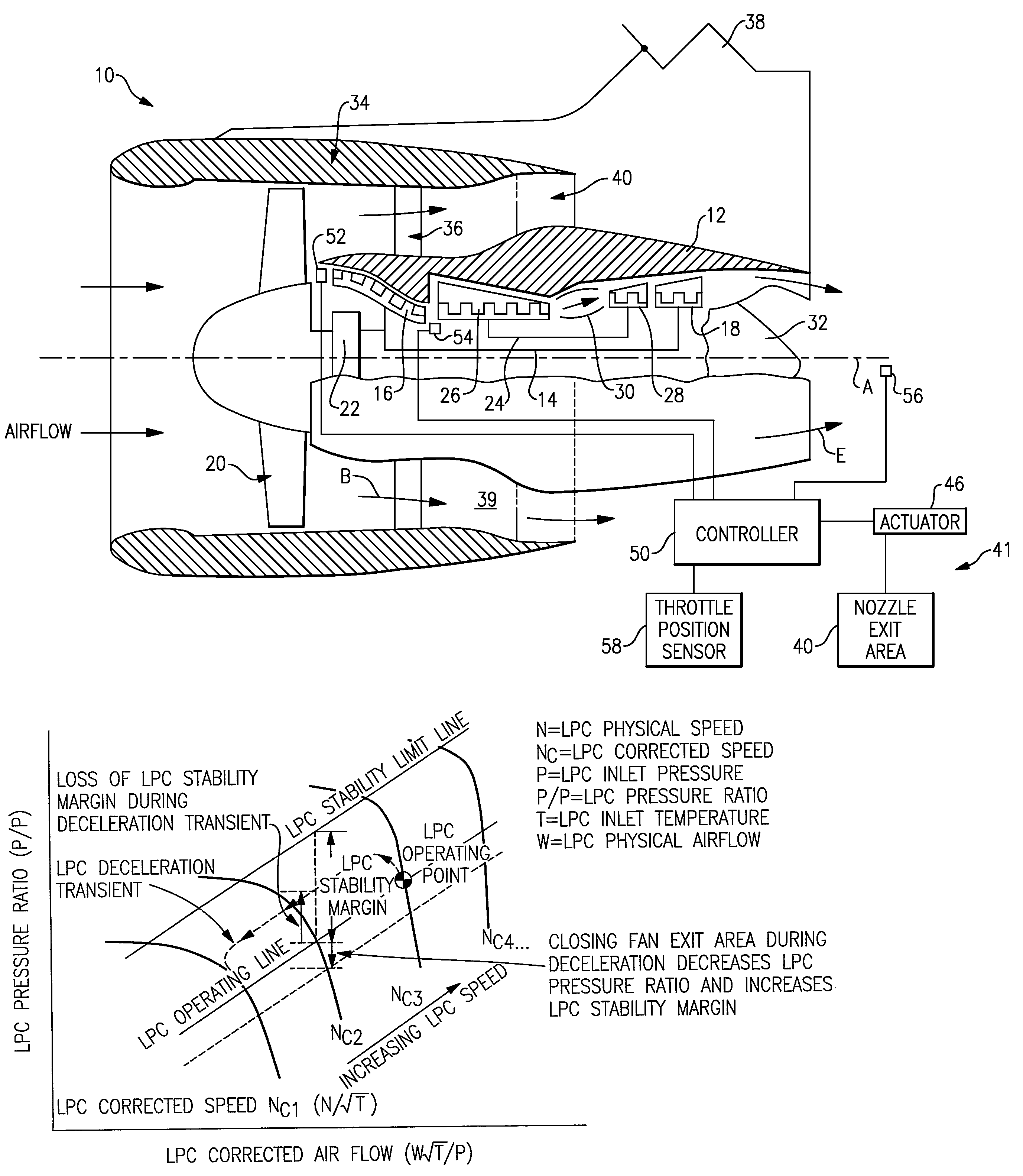
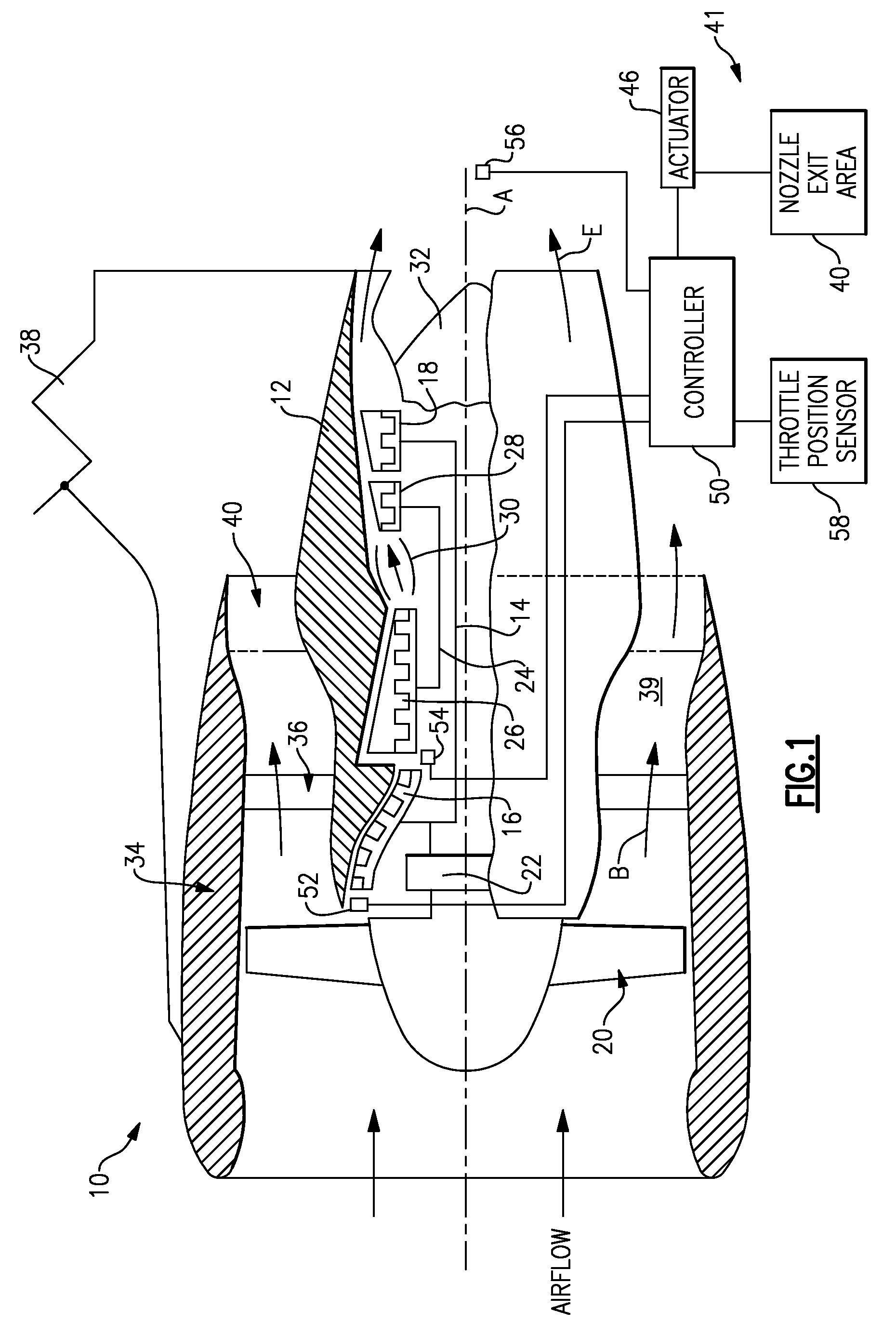
[0011]A geared turbofan engine 10 is shown in FIG. 1. A pylon 38 mounts the engine 10 to an airplane. The engine 10 includes a core nacelle 12 that houses a low spool 14 and high spool 24 rotatable about an axis A. The low spool 14 supports a low pressure compressor 16 and low pressure turbine 18. In the example, the low spool 14 drives a turbofan 20 through a gear train 22. The high spool 24 supports a high pressure compressor 26 and high pressure turbine 28. A combustor 30 is arranged between the high pressure compressor 26 and high pressure turbine 28. Compressed air from compressors 16, 26 mixes with fuel from the combustor 30 and is expanded in turbines 18, 28.

[0012]In the examples shown, the engine 10 is a high bypass turbofan arrangement. In one example, the bypass ratio is greater than 10, and the turbofan diameter is substantially larger than the diameter of the low pressure compressor 16. The low pressure turbine 18 has a pressure ratio that is greater than 5, in one examp...


PUM


Abstract

A turbofan engine control system is provided for managing a low pressure compressor operating line. The engine includes a low spool having a low pressure compressor housed in a core nacelle. A turbofan is coupled to the low spool. A fan nacelle surrounds the turbofan and core nacelle and provides a bypass flow path having a nozzle exit area. A controller is programmed to effectively change the nozzle exit area in response to an undesired low pressure compressor stability margin which can result in a stall or surge condition. In one example, the physical nozzle exit area is decreased at the undesired stability condition occurring during engine deceleration. A low pressure compressor pressure ratio, low spool speed and throttle position are monitored to determine the undesired stability margin.

Description

BACKGROUND OF THE INVENTION[0001]This application claims priority to PCT Application Serial No. PCT / US2006 / 039808, filed on Oct. 12, 2006.[0002]This invention relates to a turbofan engine, and more particularly, the invention relates to managing the operational line of a low pressure compressor.[0003]A typical turbofan engine includes low and high spools. The low spool is coupled to a turbofan and typically supports a low pressure turbine and low pressure compressor. The high spool rotates relative to the low spool and typically supports a high pressure compressor downstream of the low pressure compressor and is coupled to a high pressure turbine upstream of the low pressure turbine. The spools, turbine and compressor are housed in a core nacelle. The turbofan is arranged upstream from the core nacelle. A fan nacelle surrounds the turbofan and core nacelle to provide a bypass flow path.[0004]Maintaining aerodynamic stability of the low pressure compressor is a significant factor for...

Claims


Application Information

Patent Timeline
Patent Type & Authority Patents(United States)
IPC IPC(8): F02C9/28F02K1/12F02K3/075
CPCF01D17/08F01D17/141F01D21/00F02K1/1207F02K1/15F02K1/16F02K3/06F02K3/075F05D2270/101F05D2270/304F05D2270/3013F05D2270/301F05D2250/52
Inventor HURWITZ, WAYNEMCVEY, WILLIAM J.
Owner RTX CORP
Why Eureka
Try Eureka