Method and system adjusting an exhaust heat recovery valve

a heat recovery valve and exhaust heat technology, applied in the direction of machines/engines, output power, electric control, etc., can solve the problems of difficult control of turbocharger compressor surge under some engine operating conditions, degraded performance of the exhaust heat recovery valve, and increased turbocharger output power, etc., to increase engine efficiency, reduce engine displacement, and boost the effect of the engin

Active Publication Date: 2013-12-10
FORD GLOBAL TECH LLC
View PDF11 Cites 69 Cited by
  • Summary
  • Abstract
  • Description
  • Claims
  • Application Information

AI Technical Summary

Benefits of technology

[0002]One way to increase engine efficiency is to reduce engine displacement and boost the engine. By boosting the engine, the engine air capacity can be increased such that additional fuel may be supplied to the engine to increase engine power output. However, it may be possible for a turbocharger waste-gate to degrade in performance during engine operation. For example, a waste-gate range of motion may be reduced during some operating conditions. If the waste-gate does not open as far as is desired, it may be difficult to control turbocharger compressor surge under some engine operating conditions. Further, the turbocharger may produce more boost than is desired during some engine operating conditions when the waste-gate range of motion is less than desired.
[0004]By adjusting the position of a heat recovery valve in an exhaust system, it may be possible to control engine boosting and turbocharger compressor surge when a turbocharger waste-gate range of operation is degraded. In one example, if a turbocharger waste-gate is stuck in a closed position, a heat recovery valve position is adjusted such that a portion of exhaust gas energy bypasses a turbocharger turbine. Alternatively, if the turbocharger waste-gate opening amount is restricted to less than its full range of authority, the heat recovery valve can be opened in response to a condition where the waste-gate opening becomes limited. For example, if a turbocharger waste-gate freely opens to 25% if its full opening range, but if the waste-gate fails to open beyond 30% if its full opening range, the heat recovery valve may be opened further when the waste-gate position is commanded to a position that is greater than 30% of the waste-gate opening range. In this way, it is possible for an exhaust heat recovery valve to assist in controlling turbocharger boost and surge when operation of a turbocharger waste-gate becomes degraded.
[0005]The present description may provide several advantages. In particular, the approach provides an alternative or additional way to control engine boost and turbocharger compressor surge. In addition, the engine system may not have to reduce engine output as much as when a heat recovery valve is not available to control boost and compressor surge. Further still, in some examples, the heat recovery valve may be used to control turbocharger operation when the waste-gate is operating as desired but where the waste-gate position is not adjustable due to a low level of boost or due to a low level of actuation force (e.g., low vacuum pressure).

Problems solved by technology

However, it may be possible for a turbocharger waste-gate to degrade in performance during engine operation.
If the waste-gate does not open as far as is desired, it may be difficult to control turbocharger compressor surge under some engine operating conditions.
Further, the turbocharger may produce more boost than is desired during some engine operating conditions when the waste-gate range of motion is less than desired.

Method used


Image

  • Method and system adjusting an exhaust heat recovery valve
  • Method and system adjusting an exhaust heat recovery valve
  • Method and system adjusting an exhaust heat recovery valve

Examples


Embodiment Construction

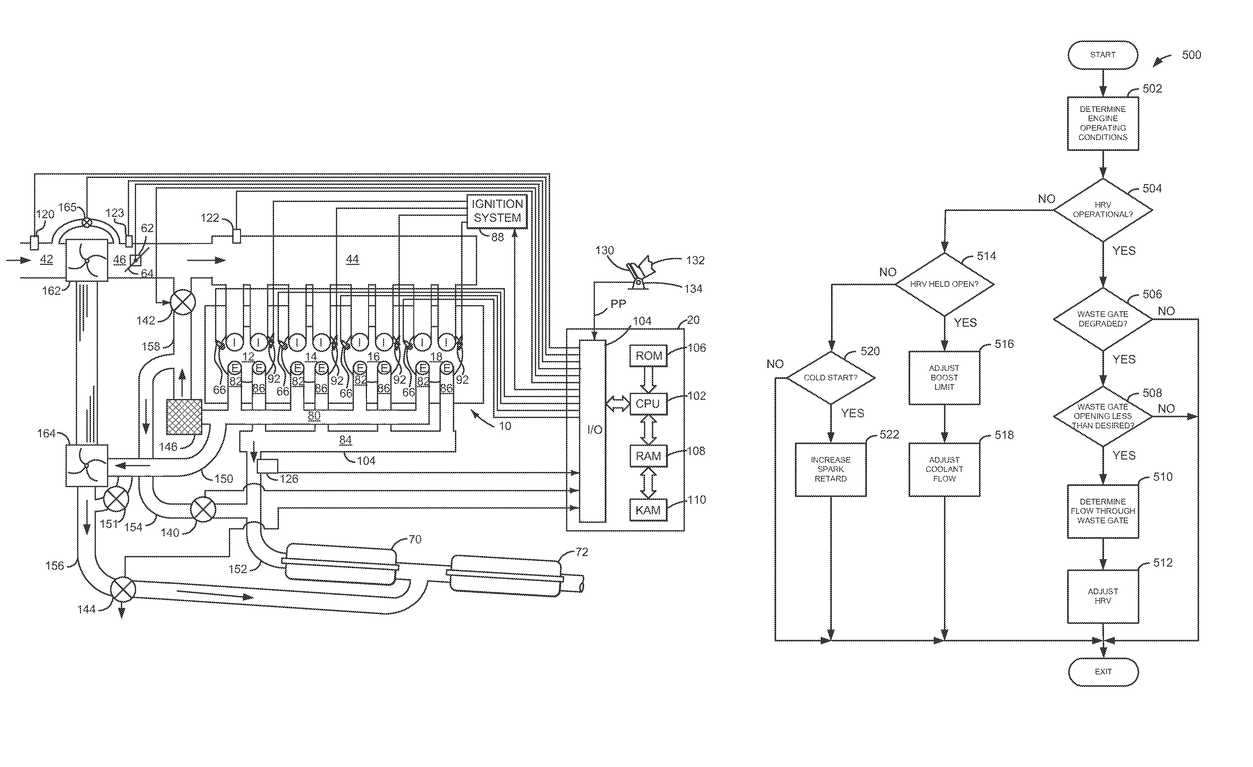
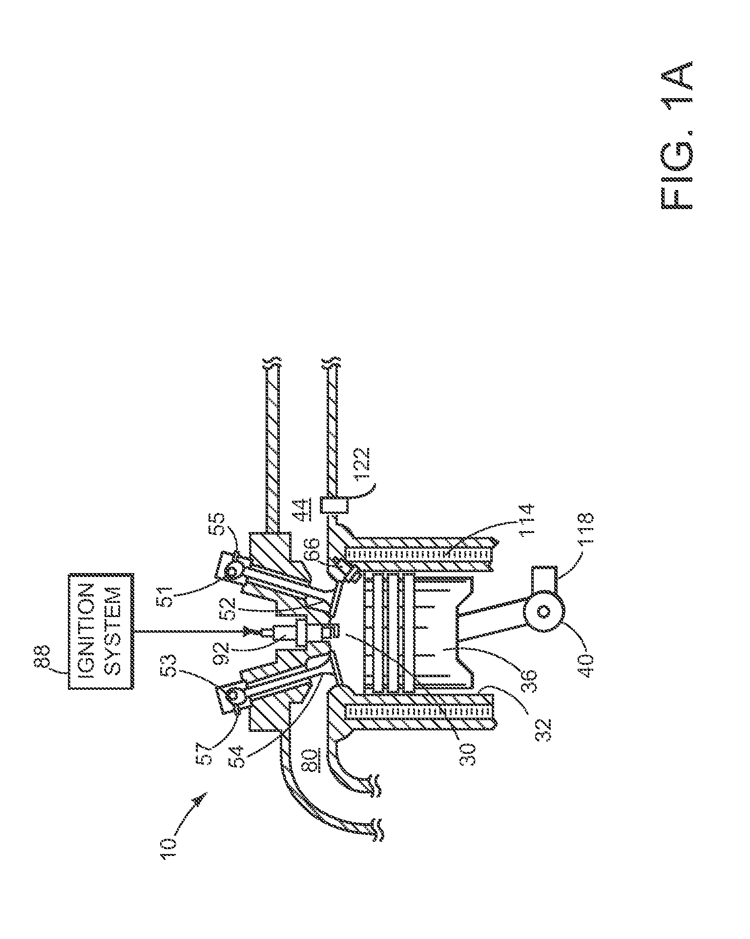
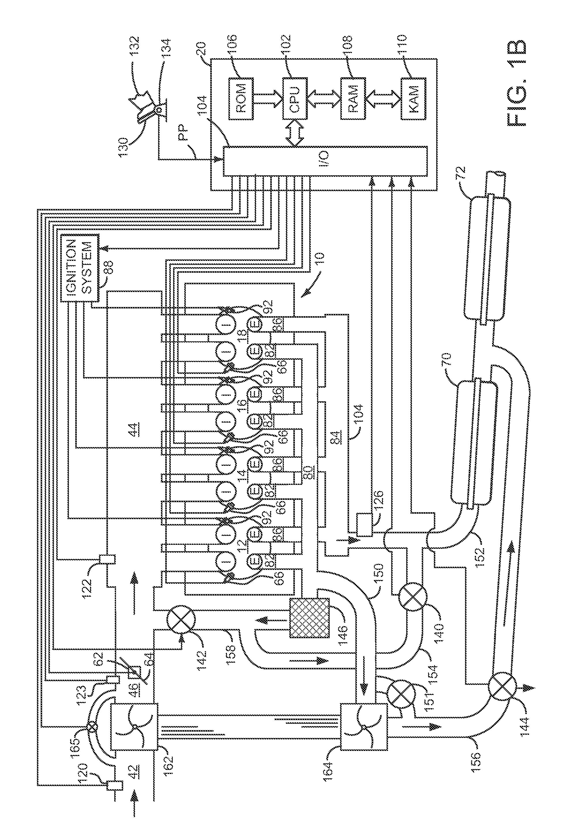
[0016]The present description is related to operating an engine. In one non-limiting example, the engine may be configured as illustrated in FIGS. 1A and 1B. In one example, blow-down gases of a cylinder are separated from residual cylinder gases and the engine is operated according to the methods of FIGS. 4A-4B providing the signals of FIGS. 2-3. Further, if operation of a turbocharger waste-gate or vane position adjustment degrades, a heat recovery valve is operated according to the method of FIG. 5 to operate similar to a waste-gate, thereby allowing the engine boost to be controlled.

[0017]Referring to FIG. 1A, a single cylinder of an internal combustion engine 10 is shown. Internal combustion engine 10 is comprised of a plurality of cylinders as shown in FIG. 2. Engine 10 includes combustion chamber 30, coolant sleeve 114, and cylinder walls 32 with piston 36 positioned therein and connected to crankshaft 40. Combustion chamber 30 is shown communicating with intake manifold 44 a...


PUM


Abstract

A method for adjusting an exhaust heat recovery valve is presented. In one embodiment, the method may control an amount of boost provided by a turbocharger to an engine.

Description

FIELD[0001]The present description relates to a method for adjusting an exhaust heat recovery valve. The method and system may be particularly useful for a turbocharged engine.BACKGROUND AND SUMMARY[0002]One way to increase engine efficiency is to reduce engine displacement and boost the engine. By boosting the engine, the engine air capacity can be increased such that additional fuel may be supplied to the engine to increase engine power output. However, it may be possible for a turbocharger waste-gate to degrade in performance during engine operation. For example, a waste-gate range of motion may be reduced during some operating conditions. If the waste-gate does not open as far as is desired, it may be difficult to control turbocharger compressor surge under some engine operating conditions. Further, the turbocharger may produce more boost than is desired during some engine operating conditions when the waste-gate range of motion is less than desired.[0003]The inventors herein ha...

Claims


Application Information

Patent Timeline
Patent Type & Authority Patents(United States)
IPC IPC(8): F02D23/00
CPCF02D13/0249F02D13/0257F02D23/00F02D41/0007F02M25/0707F02D41/005F02D41/0065F02D41/0245F02M25/0726F02P5/1516Y02T10/144Y02T10/18F02D13/0242F02D23/005F02M26/05F02M26/22Y02T10/12
Inventor PURSIFULL, ROSS DYKSTRAULREY, JOSEPH NORMAN
Owner FORD GLOBAL TECH LLC
Why Eureka
Try Eureka