Rasterization tile coalescer and reorder buffer

a rasterization tile and buffer technology, applied in the field of graphics processing, can solve the problems of reducing the throughput of a graphics pipeline, inefficient non-local memory access operations, etc., and achieve the effect of reducing memory access latencies

Active Publication Date: 2013-12-10
NVIDIA CORP
View PDF11 Cites 25 Cited by
  • Summary
  • Abstract
  • Description
  • Claims
  • Application Information

AI Technical Summary

Benefits of technology

[0009]One advantage of the invention is that collecting samples of graphic data into bins allows memory access operations performed when process

Problems solved by technology

Non-local memory access operations are inefficient a

Method used


Image

  • Rasterization tile coalescer and reorder buffer
  • Rasterization tile coalescer and reorder buffer
  • Rasterization tile coalescer and reorder buffer

Examples


Embodiment Construction

[0023]In the following description, numerous specific details are set forth to provide a more thorough understanding of the present invention. However, it will be apparent to one of skill in the art that the present invention may be practiced without one or more of these specific details. In other instances, well-known features have not been described in order to avoid obscuring the present invention.

System Overview

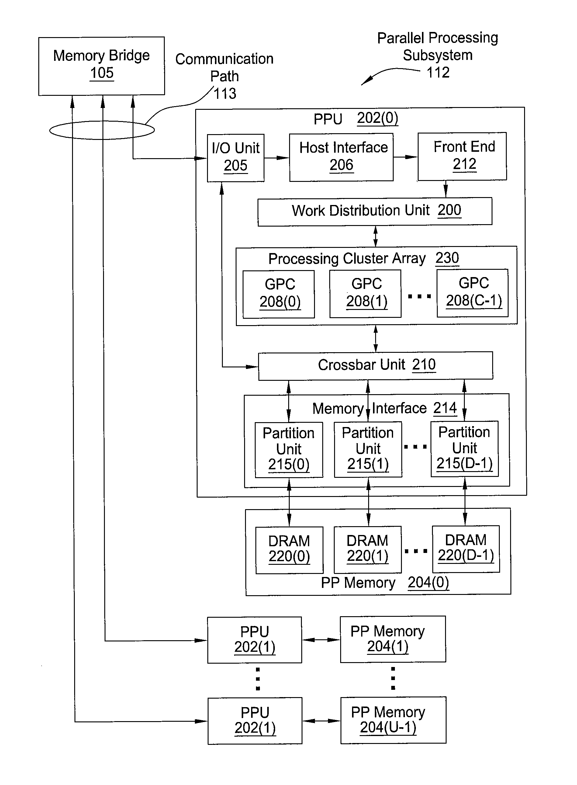
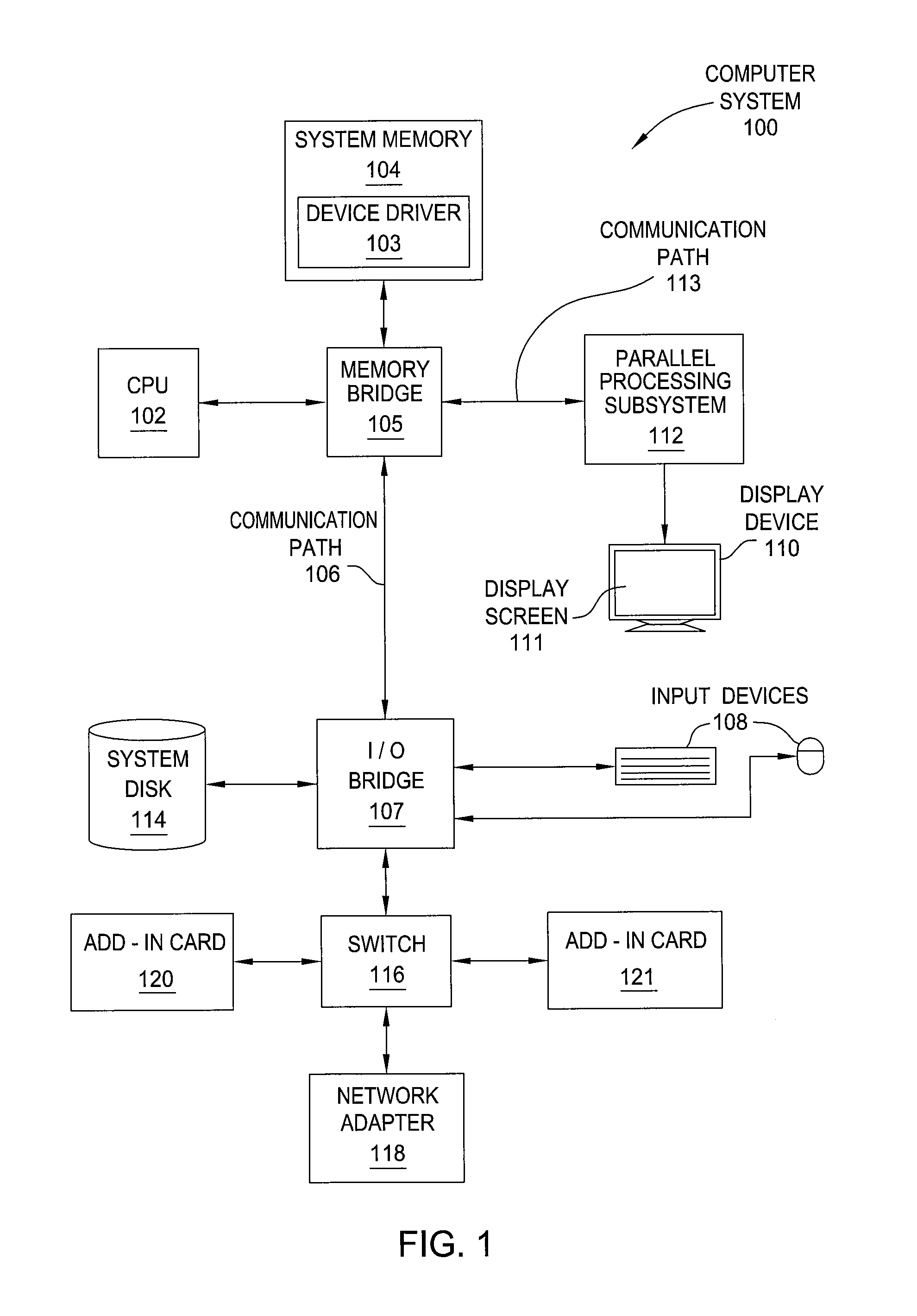
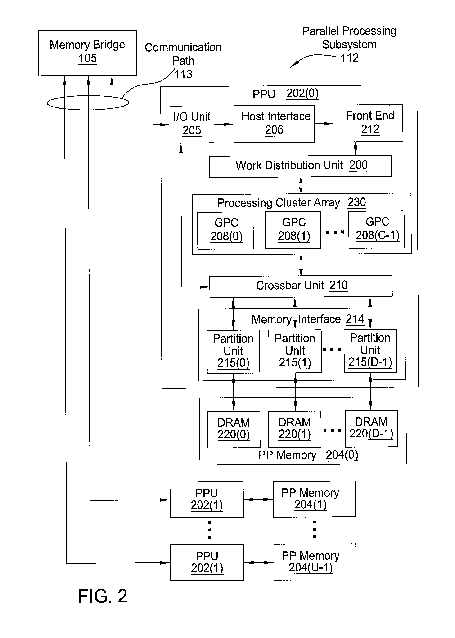
[0024]FIG. 1 is a block diagram illustrating a computer system 100 configured to implement one or more aspects of the present invention. Computer system 100 includes a central processing unit (CPU) 102 and a system memory 104 communicating via an interconnection path that may include a memory bridge 105. Memory bridge 105, which may be, e.g., a Northbridge chip, is connected via a bus or other communication path 106 (e.g., a HyperTransport link) to an I / O (input / output) bridge 107. I / O bridge 107, which may be, e.g., a Southbridge chip, receives user input from one or mor...


PUM


Abstract

A raster unit generates graphic data for specific regions of a display device by processing each graphics primitive in a sequence of graphics primitives. A tile coalescer within the raster unit receives graphic data based on the sequence of graphics primitives processed by the raster unit. The tile coalescer collects graphic data for each region of the display device into a different bin before shading and then outputs each bin separately.

Description

CROSS-REFERENCE TO RELATED APPLICATIONS[0001]This application claims the benefit of United States provisional patent application titled “Rasterization Tile Coalescer and Reorder Buffer,” filed on Oct. 8, 2009 and having Ser. No. 61 / 249,923.BACKGROUND OF THE INVENTION[0002]1. Field of the Invention[0003]Embodiments of the present invention relate generally to graphics processing, and, more specifically, to a rasterization tile coalescer and reorder buffer.[0004]2. Description of the Related Art[0005]In a conventional graphics pipeline, graphics primitives are received by a raster unit in a specific order, known as “API order.” The raster unit rasterizes each graphics primitive into samples that reside within one or more specific screen regions, referred to as “screen tiles,” and then sends a “packet” of samples associated with each screen tile to downstream units for further processing. The downstream units may perform memory access operations for each received packet.[0006]When rast...

Claims


Application Information

Patent Timeline
IPC IPC(8): G09G5/00
CPCG09G5/00G06T15/005G06T11/40G09G5/363
Inventor PURCELL, TIMOTHY JOHNMOLNAR, STEVEN E.
Owner NVIDIA CORP
Why Eureka
Try Eureka