Signal processing apparatus and method, noise reduction apparatus and method, and program therefor

a signal processing and noise reduction technology, applied in the field of signal processing apparatus and method, can solve the problems of insufficient noise reduction of methods, increase in ccd sensitivity, and inability to reduce the noise appropriately, so as to achieve the effect of reducing noise, reducing the noise in each color component image obtained from a ccd-raw image, and high quality

Inactive Publication Date: 2013-12-10
FUJIFILM CORP
View PDF14 Cites 0 Cited by
  • Summary
  • Abstract
  • Description
  • Claims
  • Application Information

AI Technical Summary

Benefits of technology

[0013]In the present invention, the first noise reduction processing is performed on an image, in which each of multitudes of pixels has one of a plurality of color components, and the color components are distributed regularly, i.e., a raw image so-called CCD-RAW image, based only on pixel arrangement. This allows noise in each of the color component images obtained from a CCD-RAW image may be reduced even when a large amount noise is contained in the CCD-RAW image as in high sensitivity photographing. Consequently, each of the color component images may be classified accurately into a plurality of groups according to the comparison result without being affected by the noise.
[0014]Further, noise reduction processing may be performed appropriately according to the classified groups, so that a high quality image with reduced noise may be obtained.
[0015]Still further, the first noise reduction is performed based only on pixel arrangement, i.e., without regarding the distribution of the color components, so that the first noise reduction processing is performed, in effect, in the frequency band greater than or equal to Nyquist frequency of each of the color components included in an image. Consequently, an image subjected to the noise reduction processing may possibly be blurred slightly, but the blur is reduced in each of the color component images obtained by separating the image into each of the color components. This allows each of the color component images to be classified into a plurality of groups according to the comparison result without being affected by the blur.
[0021]This may reduce noise in an image without blurring an edge or the like, since the filtering processing by the low-pass filter is not performed in a direction that crosses the edge or the like where signal values varies.
[0023]Here, signal values in an image may vary gradually like gradation, abruptly like an edge, or finely like a pattern on clothing, and frequency characteristics differ in each case. Consequently, by performing filtering processing by a plurality of types of high-pass filters having different frequency characteristics from each other to obtain a plurality of filtering results and detecting a direction in which variance of the signal values is smallest based on the plurality of filtering results, directions in which signal values vary according to various variation modes. Accordingly, the direction in which variance of the signal values is smallest may be detected more adequately, and noise in an image may be reduced more accurately without blurring an edge or the like.

Problems solved by technology

The increase in the sensitivity of CCD's, however, has given rise to a problem of noise included in images obtained by photographing.
The method described in U.S. Patent Application Publication No. 20050099515 reduces the noise only by smoothing processing, though noise amount is estimated with respect to each pixel, so that the method could not reduce the noise appropriately when the amount of noise is large.
In the mean time, the method described in U.S. Patent Application Publication No. 20060039039 could cause an image to be blurred when the photographing sensitivity is increased and hence the noise amounts to a large amount, since in such a case, distinction between the noise and signals of edges and the like is difficult or the correlation between each color component becomes small.

Method used


Image

  • Signal processing apparatus and method, noise reduction apparatus and method, and program therefor
  • Signal processing apparatus and method, noise reduction apparatus and method, and program therefor
  • Signal processing apparatus and method, noise reduction apparatus and method, and program therefor

Examples


first embodiment

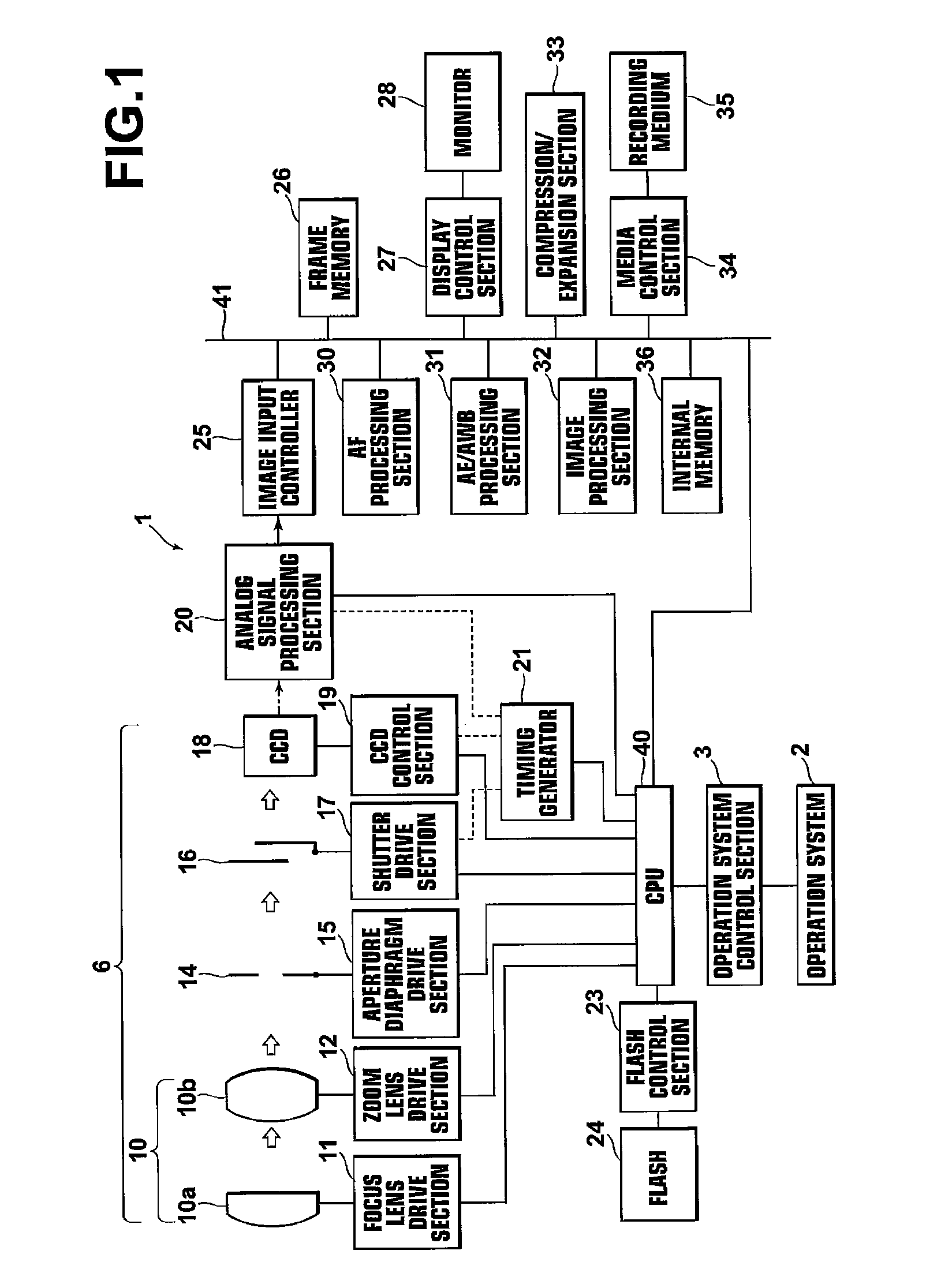
[0053]Hereinafter, exemplary embodiments of the present invention will be described with reference to the accompanying drawings. FIG. 1 is a schematic block diagram of a digital camera to which a signal processing apparatus and noise reduction apparatus according to the present invention is applied, illustrating the construction thereof. As shown in FIG. 1, the digital camera 1 includes an operation system 2 having an operation mode switch, a zoom-lever, an up-down and right-left button, a release button, a power switch, and the like, and an operation system control section 3, which is an interface for transferring operational contents of the operation system 2 to a CUP 40.

[0054]An imaging system 6 includes a focus lens 10a and a zoom lens 10b that constitute a taking lens 10. The respective lenses are movable in the optical axis directions by a focus lens drive section 11 and a zoom-lens drive section 12 respectively, each of which including a motor and a motor driver. The focus le...

second embodiment

[0124]FIG. 14 is a conceptual diagram illustrating processing performed by a gradient discrimination filtering section 67 in the As illustrated in FIG. 14, the gradient discrimination filtering section 67 performs filtering processing on each pixel of the color component images RL, GL, and BL by high-pass filtering (H-pass) sections 70A to 70D in the H, V, NE and NW directions respectively, and calculates their absolute values by absolute value calculation sections (abs) 71A to 71D as evaluation values Q_H, Q_V, Q_NE, and Q_NW respectively.

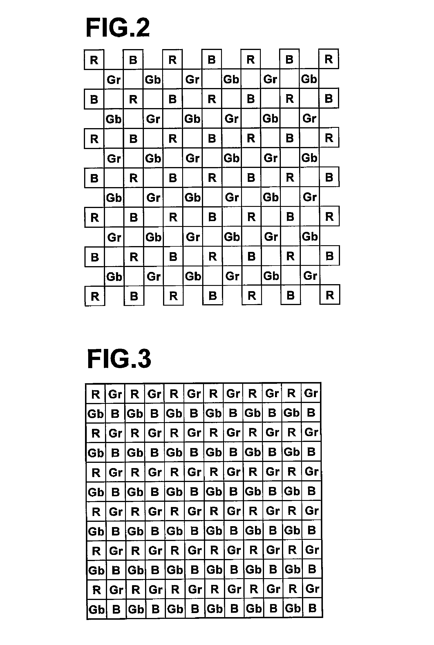
[0125]Here, if the CCD 18 is a CCD having the honeycomb arrangement shown in FIG. 2, the filtering processing by the high-pass filters (high-pass filtering processing) is filtering processing using each pixel adjacent to the target pixel located in the center, as shown in FIG. 15A. If the CCD 18 is a CCD having the Beyer arrangement shown in FIG. 3, the filtering processing by the high-pass filters is filtering processing using each pixel adjacen...

third embodiment

[0134]FIG. 16 is a conceptual diagram illustrating processing performed by the gradient discrimination filtering section 68 according to the As illustrated in FIG. 16, the gradient discrimination filtering section 68 performs filtering processing on each pixel of the color component images RL, GL, and BL by first high-pass filtering (H-pass1) sections 75A to 75D in the H, V, NE, and NW directions respectively, and calculates their absolute values by absolute value calculation sections (abs) 76A to 76D as evaluation values Q_H1, Q_V1, Q_NE1, and Q_NW1 respectively. Further, it performs filtering processing on each pixel of the color component images RL, GL, and BL by second high-pass filtering (H-pass2) sections 77A to 77D in the H, V, NE and NW directions respectively, and calculates their absolute values by absolute value calculation sections (abs) 78A to 78D as evaluation values Q_H2, Q_V2, Q_NE2, and Q_NW2 respectively.

[0135]Then, the first gradient evaluation values Q_H1, Q_V1,...


PUM


Abstract

A signal processing apparatus including: a first noise reduction processing section that performs first noise reduction processing on an image, in which each of multitudes of pixels has one of a plurality of color components and the color components are distributed regularly, based only on pixel arrangement to obtain a first processed image; a color component separation section that separates the first processed image into each of the color components to obtain a plurality of color component images; and a signal classification section that compares a signal value of a target pixel for processing with a signal value of each pixel included in a predetermined range of area around the target pixel and classifies each pixel within the predetermined range of area into one of a plurality of groups based on the comparison result.

Description

BACKGROUND OF THE INVENTION[0001]1. Field of the Invention[0002]The present invention relates to a signal processing apparatus and method for classifying an image into a plurality of groups according to the magnitude of signal values of the image, a noise reduction apparatus and method for performing noise reduction processing, and a computer program product for causing a computer to perform the signal processing method and noise reduction method.[0003]2. Description of the Related Art[0004]Pixel density and sensitivity of CCD's used in digital cameras and the like are ever increasing. The increase in the sensitivity of CCD's, however, has given rise to a problem of noise included in images obtained by photographing. Consequently, various methods have been proposed for reducing noise included in images. For example, a noise reduction method in which an amount of noise in each pixel of an image is estimated, as well as imaging conditions, then the estimated mount of noise is correcte...

Claims


Application Information

Patent Timeline
Patent Type & Authority Patents(United States)
IPC IPC(8): G06K9/00G06K9/40
CPCH04N5/217H04N9/045G06T5/002G06T5/20G06T2207/20012G06T2207/10024G06T2207/20192H04N23/81H04N23/673H04N23/63H04N23/843H04N25/134
Inventor OISHI, MAKOTO
Owner FUJIFILM CORP
Why Eureka
Try Eureka