Supercharge Your Innovation With Domain-Expert AI Agents!

Relay server and relay communication system

a relay server and relay technology, applied in the field of relay server configuration, can solve the problems of not easy to build a system with expandability and flexibility, and achieve the effect of convenient terminal setting

Active Publication Date: 2013-12-10
MURATA MASCH LTD
View PDF89 Cites 0 Cited by
  • Summary
  • Abstract
  • Description
  • Claims
  • Application Information

AI Technical Summary

Benefits of technology

The present invention provides a configuration that allows for easy setting of a terminal that can share or operate resources at the respective base point. This results in a flexible relay communication network where changes in resource sharable terminals are automatically reflected on other relay servers, reducing the need for multiple relay servers to be operated separately. The technical effect of this invention is simplification of the task of changing the resource sharable terminal.

Problems solved by technology

However, this type of system tends to be rigid in terms of virtually building the network, and it is not easy to build a system having expandability and flexibility.

Method used


Image

  • Relay server and relay communication system
  • Relay server and relay communication system
  • Relay server and relay communication system

Examples


Embodiment Construction

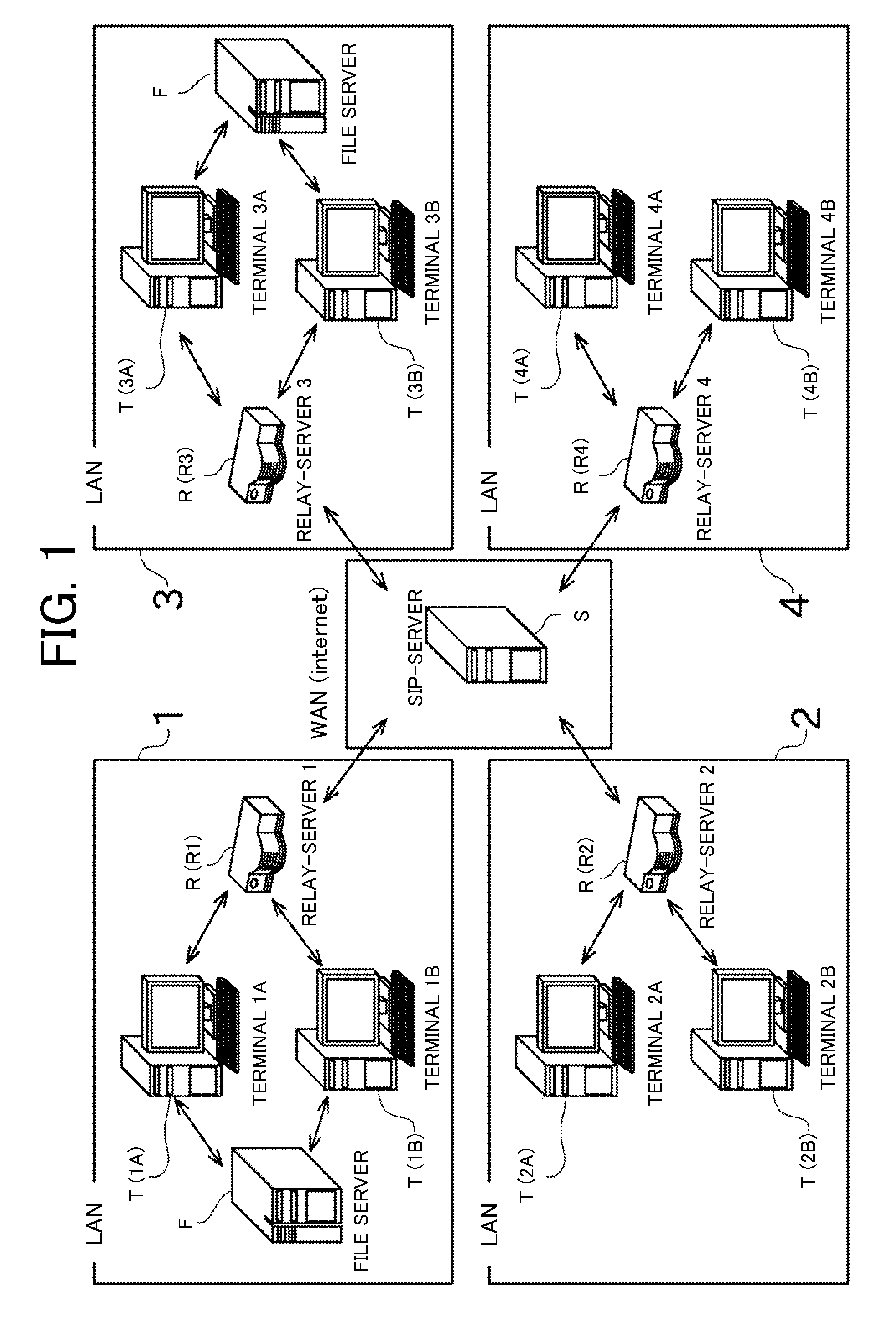
[0030]The preferred embodiments of the present invention will now be described with reference to the drawings. FIG. 1 is an explanatory view showing an overall configuration of a relay communication system according to a preferred embodiment of the present invention.

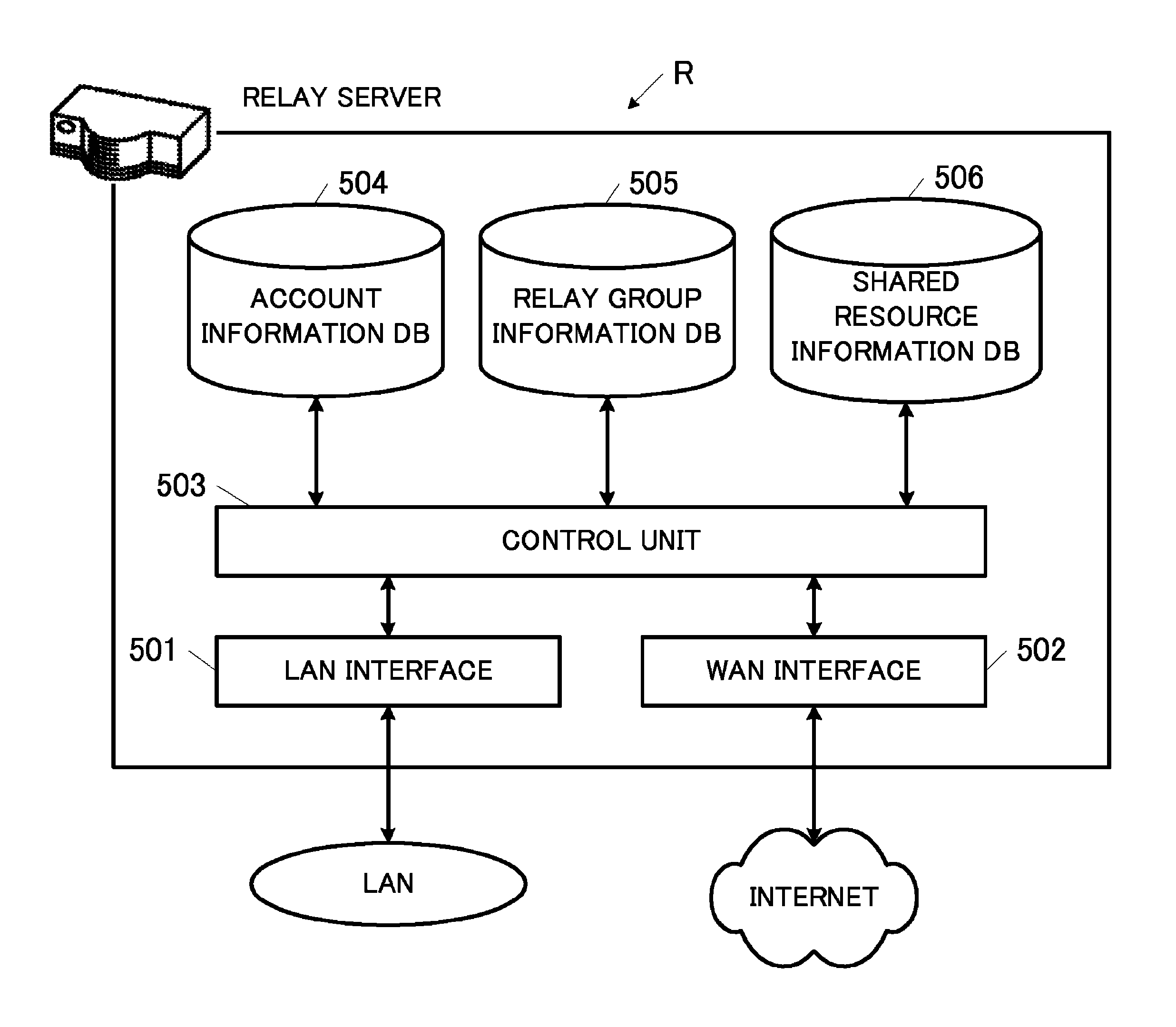
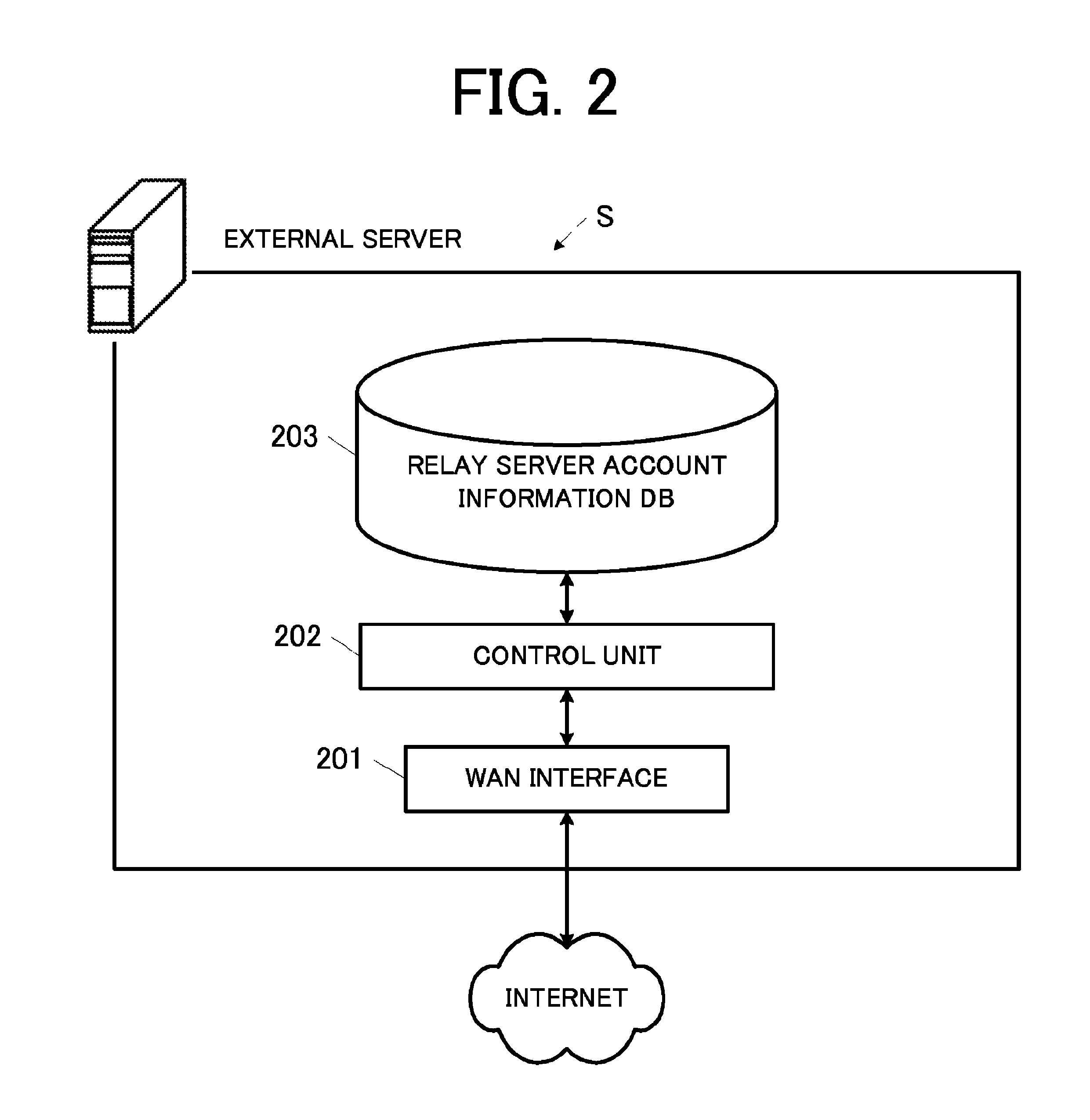
[0031]As shown in FIG. 1, the relay communication system is defined by a plurality of LANs connected to a WAN (Wide Area Network) The relay communication system includes an external server S, a relay server R, a client terminal T, a file server F, and the like.

[0032]The WAN is a network for connecting different LANs to each other. In the present preferred embodiment, the Internet is preferably used as the WAN.

[0033]The LAN is a relatively small-scale network provided in a limited location. A plurality of LANs exist, each provided at a physically remote location. In the present preferred embodiment, there is considered a case where the LAN 1 is provided at the Tokyo branch office, and LANs 2, 3, 4 are respectively provide...


PUM


Abstract

In a relay communication system, when receiving an operation instruction of a resource from a client terminal stored in an account information registration unit, a relay server relays the operation instruction to a client terminal capable of operating the resource based on relay group information if the resource is operable by another client terminal.

Description

CROSS-REFERENCE TO RELATED APPLICATIONS[0001]This application claims priority under 35 U.S.C. 119 to Japanese Patent Application No. 2007-121858, filed on May 2, 2007 and Japanese Patent Application No. 2007-152118, filed on Jun. 7, 2007, which applications are hereby incorporated by reference in their entirety.BACKGROUND OF THE INVENTION[0002]1. Field of the Invention[0003]The present invention mainly relates to a configuration of a relay server that enables communication between terminals.[0004]2. Description of the Related Art[0005]A communication technique referred to as VPN (Virtual Private Network) is known (see, e.g., Japanese Laid-Open Patent Publication No. 2002-217938). The VPN is utilized to communicate between terminals connected to a LAN (Local Area Network) of a plurality of branch offices (base points) provided in each of the regions over the Internet. Through the use of the VPN, another LAN in a remote location can be used as if it is a directly connected network.[00...

Claims


Application Information

Patent Timeline
Patent Type & Authority Patents(United States)
IPC IPC(8): G06F15/16
CPCH04L67/104H04L67/1065H04L67/1059H04L67/28H04L67/288H04L67/56
Inventor TANIMOTO, YOSHIFUMI
Owner MURATA MASCH LTD
Features
  • R&D
  • Intellectual Property
  • Life Sciences
  • Materials
  • Tech Scout
  • Unparalleled Data Quality
  • Higher Quality Content
  • 60% Fewer Hallucinations
Learn More