
Drive unit for a hair cutting machine

a drive unit and hair cutting technology, which is applied in the direction of dynamo-electric machines, electrical apparatus, metal working apparatus, etc., can solve the problems of high copper consumption of exciter coils and stamping waste of dynamo sheet metal, and the failure to achieve optimal mechanical performance of the drive uni

Active Publication Date: 2013-12-17
WAHL +1
View PDF17 Cites 2 Cited by
  • Summary
  • Abstract
  • Description
  • Claims
  • Application Information

AI Technical Summary

Benefits of technology

This patent text describes a system that increases the size of the air gap between the stator and the armature, which reduces air gap fluctuations and improves the performance of the system. Additionally, the text describes a configuration that allows for a more compact and waste-saving stamping of stator plates. The technical effects of this patent include improved system performance and more efficient manufacturing.

Problems solved by technology

One disadvantage with this design is that optimal mechanical performance of the drive unit is not achieved.
Another disadvantage is that with such a configuration, the copper consumption for the exciter coil and the stamping waste of the dynamo sheet metal, of which the stator and armature are packed, are relatively high.

Method used


Image

  • Drive unit for a hair cutting machine
  • Drive unit for a hair cutting machine
  • Drive unit for a hair cutting machine

Examples


Embodiment Construction

[0023]Matching parts in the following detailed description of the figures are labeled with the same reference numerals.

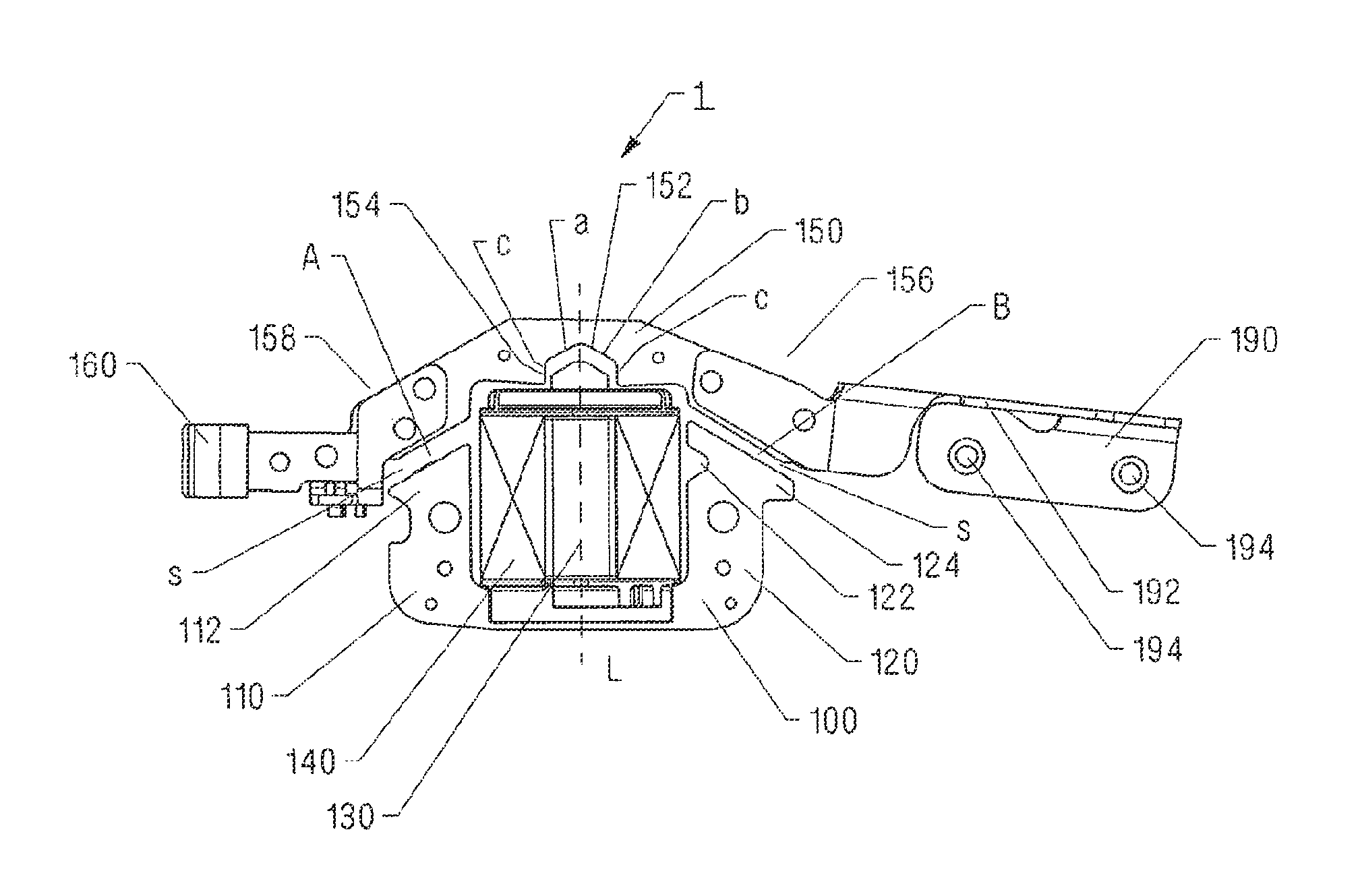
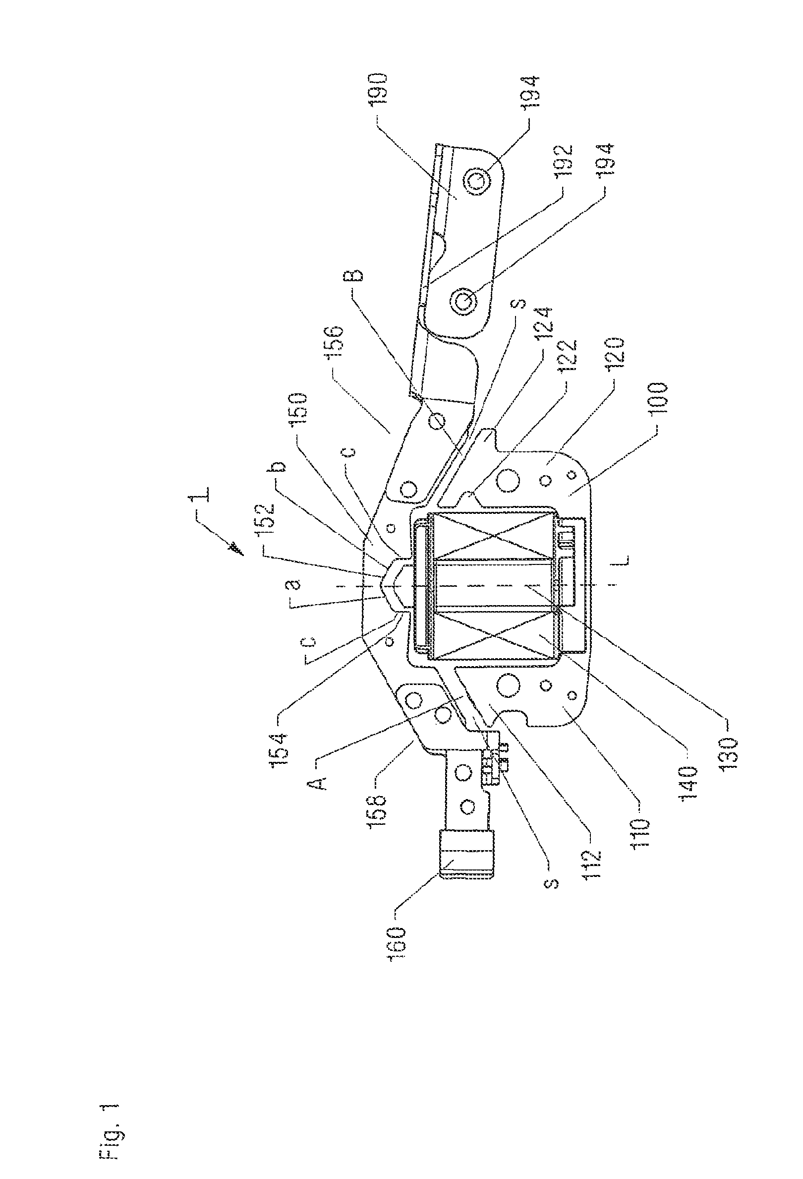
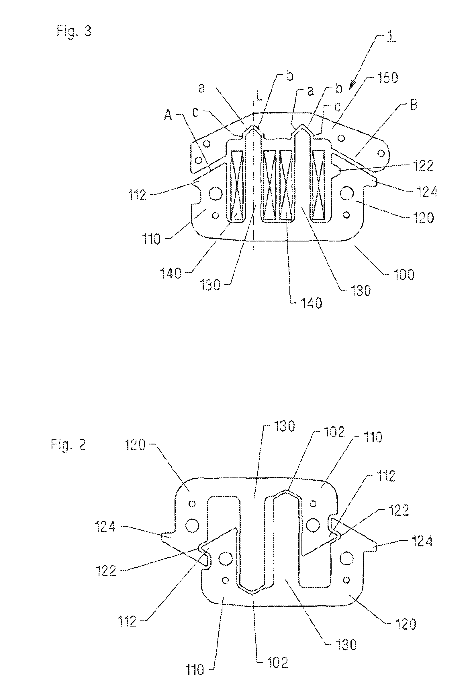
[0024]FIG. 1 shows a top view of a first exemplary embodiment of a drive unit according to the invention for a hair cutting machine having a drive motor 1. Drive motor 1 is constructed of a stator 100 having an exciter coil 140 and an armature 150 situated in such a way that it corresponds to stator 100. Stator 100 is designed to be essentially U-shaped, having a first leg 110 and a second leg 120. Exciter coil 140 sits on the periphery of an additional leg 130 situated between first leg 110 and second leg 120. Armature 150 is situated across the ends of legs 110, 120, 130 of stator 100, a tappet 160 being attached to first end 158 and a support 190 attached to second end 156. Tappet 160 has a suitable design for inducing vibration of a cutting set of a hair cutting machine and thus transmitting a movement of armature 150 to the cutting set. Support 190 is fastened ...


PUM


Abstract

A drive unit for a hair cutting machine comprises a driving motor that includes a substantially U-shaped stator which has a first leg, a second leg, and at least one additional leg located between the first leg and the second leg, at least one field coil which can be disposed on the at least one additional leg, and an armature. Lateral air gap sections are formed between the first and second leg and the armature while central air gap sections are formed between the additional leg and the armature. The central air gap sections and the lateral air gap sections extend at an angle from a longitudinal axis. A first nose, which faces away from the additional leg, is arranged at the end of the first leg, while a notch, which faces the additional leg and corresponds to the first nose, is arranged on the second leg.

Description

TECHNICAL FIELD[0001]This application relates to a drive unit for a hair cutting machine.BACKGROUND OF THE INVENTION[0002]Such drive units are fundamentally known and include a stator, an exciter coil and an armature. The stator and the armature are stamp-packed from individual insulated sheet metal layers to prevent eddy currents. The stator is designed to be essentially U-shaped and has a first leg and a second leg, an additional leg being provided between the first leg and the second leg. The exciter coil is designed as a coil for an electromagnet and is usually positioned on the at least one additional leg. The armature is situated across the legs of the stator, lateral air gap sections being provided between the first leg and the armature and between the second leg and the armature, and central air gap sections being provided between the additional leg and the armature. The central air gap sections and the lateral air gap sections run at an inclination relative to a longitudina...

Claims


Application Information

Patent Timeline
IPC IPC(8): H02K33/06B26B19/00
CPCB26B19/282H02K33/04
Inventor SCHWER, HEINRICHMULLER, STEFANKIENZLER, GERHARD
Owner WAHL
Learn More