Coordinated dimmer compatibility functions

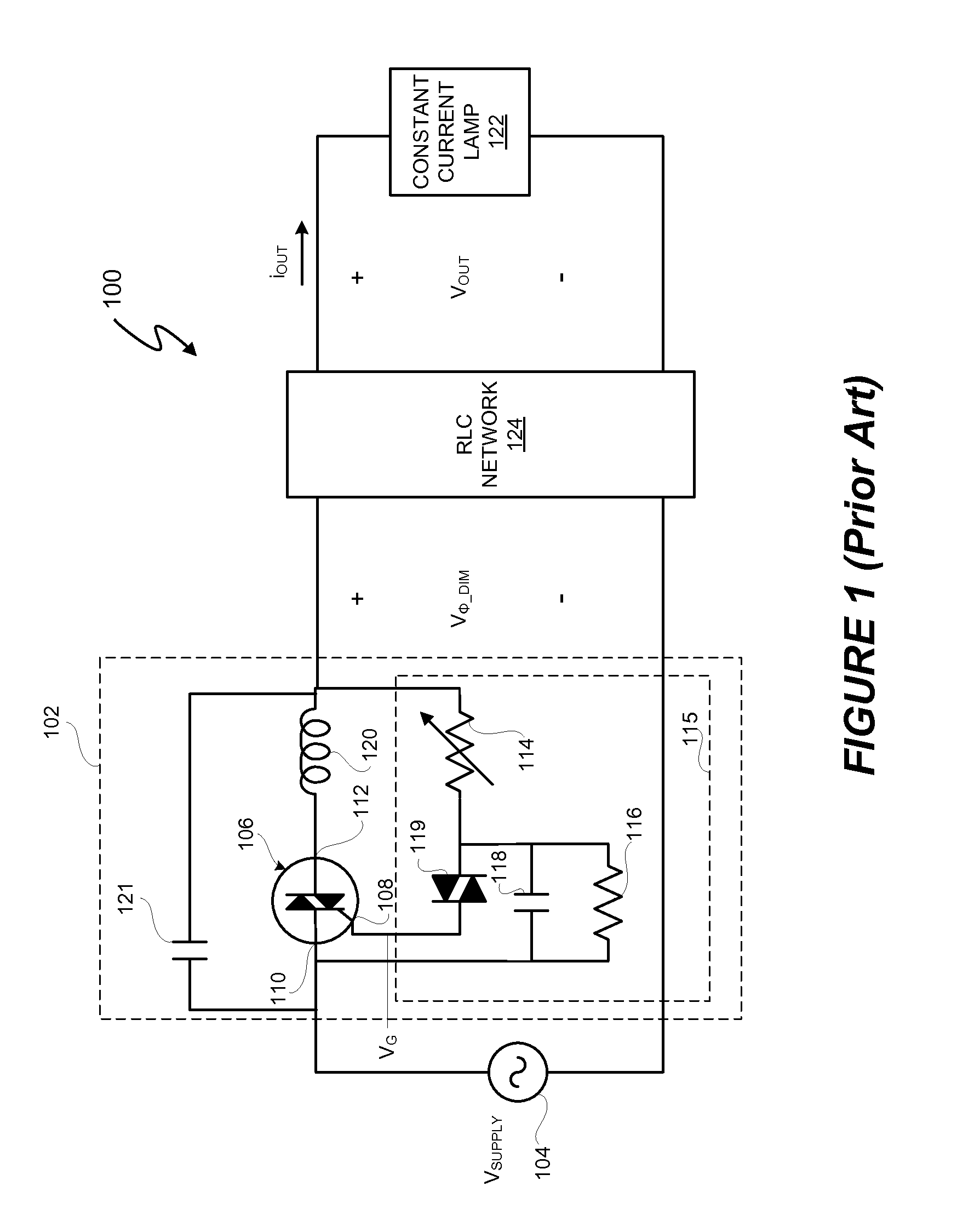
a dimmer and function technology, applied in the field of electromechanical devices, can solve the problems of inefficient rlc network b>124/b>, the edge dimmer b>102/b> does not operate ideally,

Active Publication Date: 2013-12-17
SIGNIFY HLDG BV
View PDF51 Cites 58 Cited by
  • Summary
  • Abstract
  • Description
  • Claims
  • Application Information

AI Technical Summary

Problems solved by technology

However, in many circumstances, the leading edge dimmer 102 does not operate ideally.
Although relatively simply to implement, the RLC network 124 is inefficient because of, for example, resistor-based power losses.

Method used


Image

  • Coordinated dimmer compatibility functions
  • Coordinated dimmer compatibility functions
  • Coordinated dimmer compatibility functions

Examples


Embodiment Construction

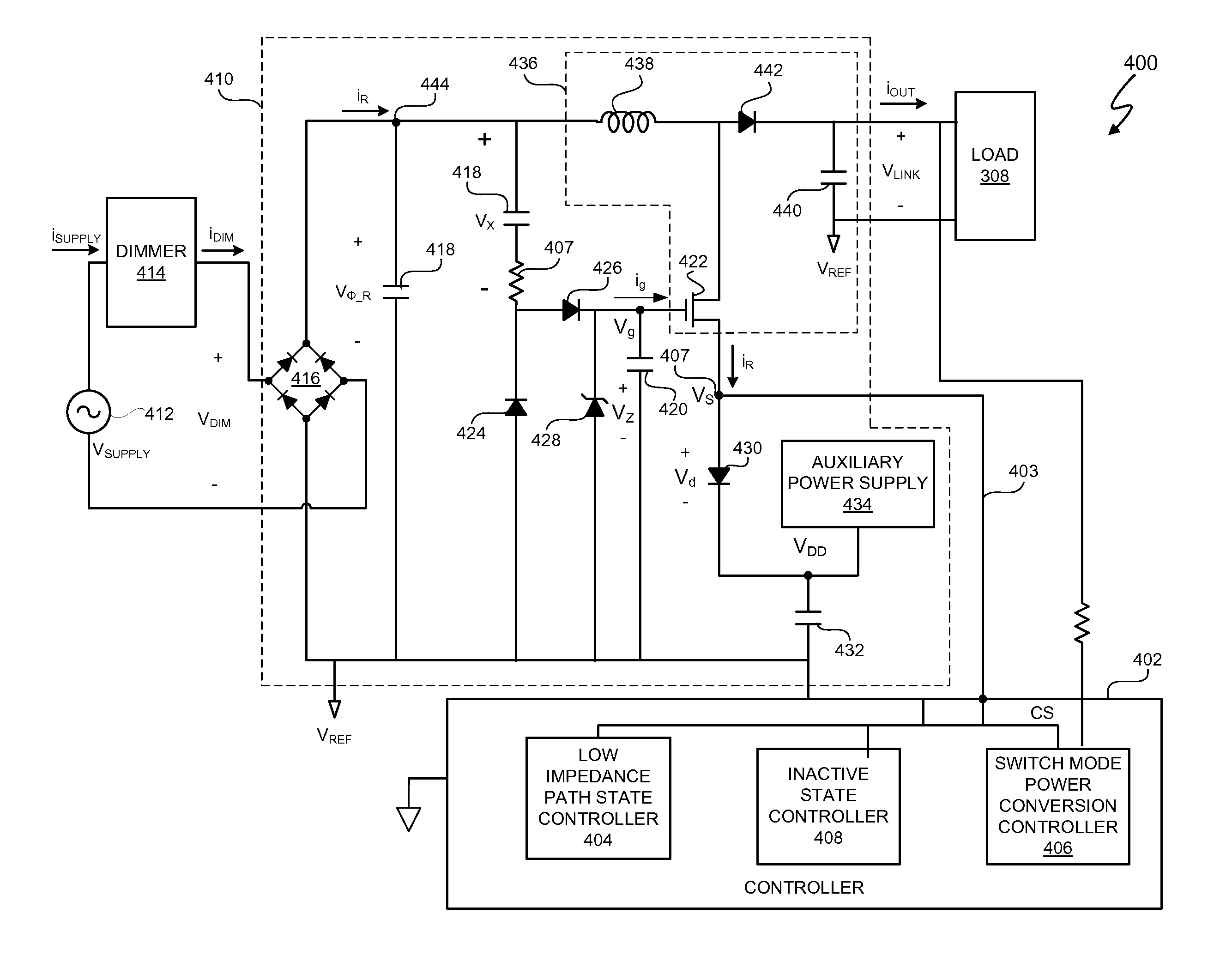
[0039]In at least one embodiment, a system and method includes a controller that is configured to coordinate (i) a low impedance path for a dimmer current, (ii), control of switch mode power conversion and (iii) an inactive state to, for example, reduce the dimmer current while allowing a dimmer to function normally from cycle to cycle of an alternating current (AC) supply voltage. In at least one embodiment, the dimmer functions normally when the dimmer conducts at a correct phase angle indicated by a dimmer input setting and avoids prematurely resetting while conducting. In at least one embodiment, by coordinating functions (i), (ii), and (iii), the controller controls a power converter system that is compatible with a triac-based dimmer. In at least one embodiment, the controller coordinates functions (i), (ii), and (iii) in response to a particular dimming level indicated by a phase cut, rectified input voltage supplied to the power converter system. In at least one embodiment, ...


PUM


Abstract

A system and method includes a controller that is configured to coordinate (i) a low impedance path for a dimmer current, (ii), control of switch mode power conversion and (iii) an inactive state to, for example, to allow a dimmer to function normally from cycle to cycle of an alternating current (AC) supply voltage. In at least one embodiment, the dimmer functions normally when the dimmer conducts at a correct phase angle indicated by a dimmer input setting and avoids prematurely resetting while conducting. In at least one embodiment, by coordinating functions (i), (ii), and (iii), the controller controls a power converter system that is compatible with a triac-based dimmer. In at least one embodiment, the controller coordinates functions (i), (ii), and (iii) in response to a particular dimming level indicated by a phase cut, rectified input voltage supplied to the power converter system.

Description

CROSS-REFERENCE TO RELATED APPLICATION[0001]This application claims the benefit under 35 U.S.C. §119(e) and 37 C.F.R. §1.78 of U.S. Provisional Application No. 61 / 369,202, filed Jul. 30, 2010, and entitled “LED Lighting Methods and Apparatuses” and is incorporated by reference in its entirety.BACKGROUND OF THE INVENTION[0002]1. Field of the Invention[0003]The present invention relates in general to the field of electronics, and more specifically to a method and system for coordinating dimmer compatibility functions.[0004]2. Description of the Related Art[0005]Electronic systems utilize dimmers to modify output power delivered to a load. For example, in a lighting system, dimmers provide an input signal to a lighting system, and the load includes one or more light sources such as one or more light emitting diodes (LEDs) or one or more fluorescent light sources. Dimmers can also be used to modify power delivered to other types of loads, such as one or more motors or one or more portab...

Claims


Application Information

Patent Timeline
Patent Type & Authority Patents(United States)
IPC IPC(8): H05B37/00H05B37/02H02M1/00H02M1/36H05B44/00
CPCH02M1/36H05B33/0815H02M2001/0006Y02B20/346Y02B20/30H05B45/3725H02M1/0006H02M3/22H02M3/33507H02M7/06
Inventor MELANSON, JOHN L.KING, ERIC J.
Owner SIGNIFY HLDG BV
Why Eureka
Try Eureka