Lamp unit with a plurality of light source and toggle remote control method for selecting a drive setting therefor

a technology of light source and remote control method, which is applied in the direction of electric variable regulation, process and machine control, instruments, etc., can solve the problem of individual lamp units being in different states unintentionally

Inactive Publication Date: 2013-12-17
SIGNIFY HLDG BV +1
View PDF11 Cites 0 Cited by
  • Summary
  • Abstract
  • Description
  • Claims
  • Application Information

AI Technical Summary

Benefits of technology

[0007]According to an embodiment of the lamp unit, the light sources are adapted to emit light of different colors, whereby the present inventive concept advantageously provides a manner for altering the present overall color state for the lamp unit. The sequence of drive settings may be chosen to power the differently colored light sources such that different desired color combinations are achieved. The lighting of a space may in this way be altered to provide a desired atmosphere, e.g. changing from a working light to a romantic light, in a user friendly way.
[0012]According to an embodiment of the lamp unit, the lamp unit further comprises a lamp base which is arranged to be fitted in a lamp socket. The lamp unit may for instance to be retrofitted in an existing light fitting or luminaire having such a lamp socket. Thus, the lamp unit according to the present invention may advantageously be used for replacing an incandescent light source or for fitting into a light fixture normally used for incandescent light sources, such as a filamented light bulb, a halogen lamp etc. This is advantageous as a user may conveniently replace expensive and inefficient incandescent light sources in existing luminaires with lamp units in accordance with the present inventive concept. Due to the integrated control unit the functionality of the lamp unit is advantageously applicable in any luminaire into which lamp socket the lamp unit is adapted to fit. The standard type lamp socket may be e.g. a traditional screw socket or a bayonet socket. In the former case, the lamp base is a traditional screw lamp base with suitable threads.
[0013]According to another aspect of the invention, there is provided a luminaire comprising at least one lamp unit according to the present inventive concept. When employing a number of lamp units according to the present inventive concept, it is of great importance to be able to reset all lamp units to a predetermined drive setting, which is advantageously achieved with the present inventive concept.

Problems solved by technology

Further, when a plurality of lamp units are employed, e.g. in a luminaire or as light spots in a room, and responding to a common switching signal, it is possible that the individual lamp units are unintentionally in different states, e.g. outputs light of different colors or directions, when the power is switched on.

Method used


Image

  • Lamp unit with a plurality of light source and toggle remote control method for selecting a drive setting therefor
  • Lamp unit with a plurality of light source and toggle remote control method for selecting a drive setting therefor
  • Lamp unit with a plurality of light source and toggle remote control method for selecting a drive setting therefor

Examples


Embodiment Construction

[0036]Embodiments according to the present inventive concept will now be described more fully hereinafter with reference to the accompanying drawings, in which certain embodiments of the invention are shown. This invention may, however, be embodied in many different forms and should not be construed as limited to the embodiments set forth herein; rather, these embodiments are provided by way of example so that this disclosure will be thorough and complete, and will fully convey the scope of the invention to those skilled in the art. Like numbers refer to like elements throughout.

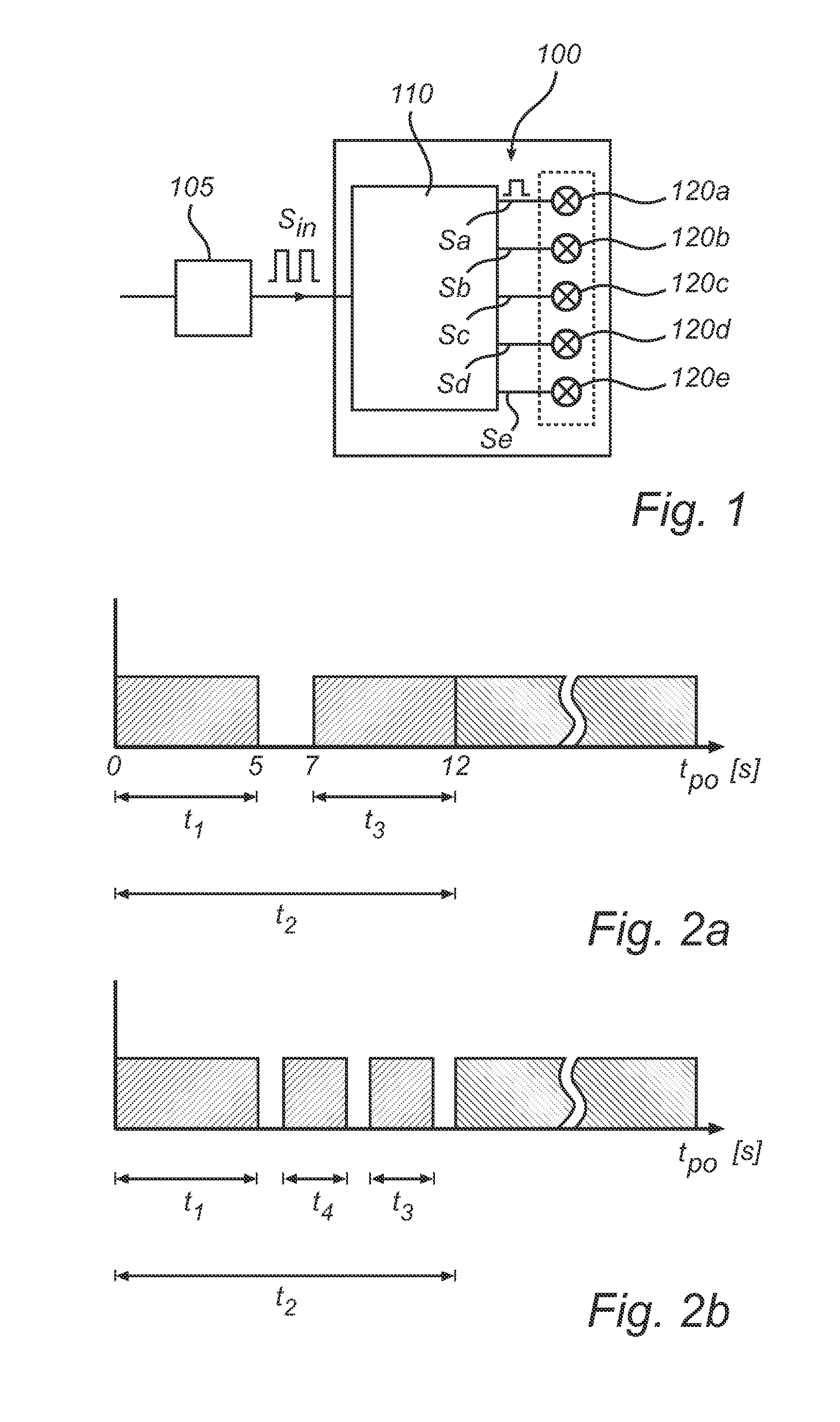
[0037]A block diagram illustrating the basic configuration of an embodiment of a lamp unit 100 according to the present invention is illustrated in FIG. 1. The lamp unit 100 comprises a plurality of light sources 120a-e, which are arranged to produce light from electricity. The light sources are here light emitting diodes, LEDs, arranged to emit light of different colors or white light. This does not rule ou...


PUM


Abstract

The present invention relates to a lamp unit (100) in which a plurality of light sources (120a-e) are controlled by means of a control unit (110) which is adapted to control a sequence of drive settings (Sa-e) for the plurality of light sources based on a switching signal (Sin) supplied to the lamp unit. The control unit is arranged such that depending on the elapsed time between deactivation of and subsequent reactivation of the switching signal, the control unit sets the current drive settings in a predetermined manner. Within a first predetermined time interval a subsequent drive setting of the light sources is employed, after a second predetermined time interval a previous drive setting of the light sources is employed, and within an intermediate time interval, arranged between the end of the first predetermined time interval and the end of the second predetermined time interval a predetermined drive setting is employed.

Description

FIELD OF THE INVENTION[0001]The present invention relates to a lamp unit comprising a plurality of light sources and a control unit adapted to control a sequence of drive settings for the light sources based on a switching signal supplied to the lamp unit, and a corresponding method for controlling a plurality of light sources based on a switching signal.BACKGROUND OF THE INVENTION[0002]It is known to manipulate the drive settings of a number of light sources by selecting a current drive setting by means of turning the power switch on and off in a particular manner. US 2007 / 0064419 A1 discloses a method for controlling the drive settings of one or more LED lights in order to provide different color states by means of a control unit and a time sensitive on-off switching method. The color states are governed by a sequence of drive settings of the LED lights. By turning the power switch off and on again within a predetermined time limit, the switching time, the next drive setting in th...

Claims


Application Information

Patent Timeline
Patent Type & Authority Patents(United States)
IPC IPC(8): H05B37/02H05B44/00
CPCH05B37/029H05B33/0863H05B45/20H05B47/155H05B47/185Y02B20/30
Inventor VAN DEN BIGGELAAR, THEODORUS JOHANNES PETRUS
Owner SIGNIFY HLDG BV
Why Eureka
Try Eureka