Method for on-site repairing of a wind turbine component

a technology for wind turbines and components, applied in the direction of motors, programme control, engine fuctions, etc., can solve the problems thus the power output of the turbine, thus reducing the aerodynamic efficiency of the blade. , to achieve the effect of reducing the maximum output power of the wind turbine, the effect of reducing the aerodynamic efficiency of the blad

Active Publication Date: 2022-03-22
SIEMENS GAMESA RENEWABLE ENERGY AS
View PDF12 Cites 0 Cited by
  • Summary
  • Abstract
  • Description
  • Claims
  • Application Information

AI Technical Summary

Benefits of technology

[0011]An aspect relates to provide a repair method for wind turbine components that can be performed on-site of wind turbine installation, that is precise and thus does not result in surface imperfections because of the repair, and that does not require replacement of the component.
[0014]The aforementioned method according to the present technique has several advantages. First, since 3D printing is sensitive, very accurate shaping of the damaged surface can be achieved as compared to user operated machine tools. Second, the shape of the damaged surface may not only be restored but may also be modified to the desired state and thus allowing advantageous alterations of the shape of the component. Third, the method using autonomous positioning mechanism obviates partially or completely any human intervention or expertise requirements and thus making the method more robust and error-free. Lastly, the method is performed at the installation site of the wind turbine and does not require dismantling of the wind turbines, and thus reducing the downtime for the repair and maintenance operations.

Problems solved by technology

Erosion of the leading edge of a turbine blade may reduce the efficiency of the blade and thus the power output by the turbine.
Wind turbine rotor blades, both of offshore wind turbines and onshore wind turbines, are especially affected by wear which occurs when the blades are impacted by particles or droplets in the ambient wind resulting in degradation of the leading edge of the wind turbine rotor blade.
The particles and droplets are present in the ambient wind and originate from dust, rain, snow-fall, etc and cause erosion of the leading edge of wind turbine blades by impingement wear resulting into reduction of the blade aerodynamic efficiency and thus the maximum output power of the wind turbine.
Erosion on a turbine blade may penetrate the structural fibre reinforced laminate leading to severe failure of the turbine blade requiring repair which can be very costly to turbine operators and may involve considerable downtime for the affected wind turbine requiring dismantling and transportation of the affected component to a repair workshop.
This holds especially true for offshore wind turbines because their maintenance costs are extremely high.
In general, an erosion protection tape will rupture due to heavy erosion, causing the layer left on the rotor blade to freely flutter in the wind.
This fluttering will result in a loss of aerodynamic performance of the blade, as well as in the generation of noise.
Thus, these solutions may not be used in the field, e.g. at offshore wind farms or at wind turbine locations are that are generally cooler or hotter than the special temperature window.
Firstly, they all require the component to be brought to repair workshops for carrying out the repair.
Secondly, the application of coating or tape or filler material is crude and leaves behind surface imperfections.
However, the protective shell once eroded also requires repair or replacement.
Repairing of the protective shell has the same two major disadvantages as aforementioned, whereas replacement is costly and time consuming.
Furthermore, the protective shells are often in multiple small pieces that are combined on the blade producing joints that are sensitive.
Third, the method using autonomous positioning mechanism obviates partially or completely any human intervention or expertise requirements and thus making the method more robust and error-free.

Method used


Image

  • Method for on-site repairing of a wind turbine component
  • Method for on-site repairing of a wind turbine component
  • Method for on-site repairing of a wind turbine component

Examples


Embodiment Construction

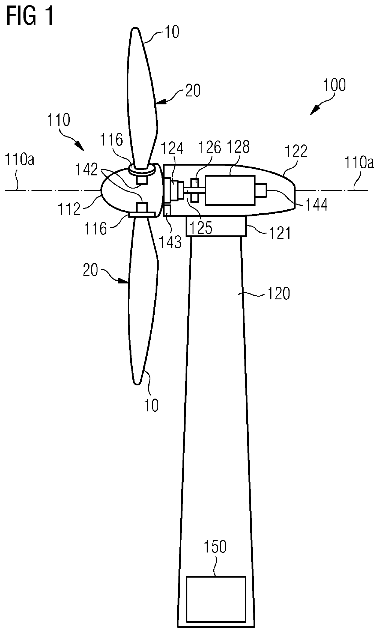
[0027]FIG. 1 shows an exemplary embodiment of a wind turbine 100 of the present technique. The wind turbine 100 includes a tower 120, which is mounted on a fundament (not shown). A nacelle 122 is mounted on top of the tower 120 and rotatable with regard to the tower 120 by means of a yaw angle adjustment mechanism 121 such as yaw bearings and yaw motors. The yaw angle adjustment mechanism 121 functions to rotate the nacelle 122 around a vertical axis (not shown) referred to as a yaw axis, which is aligned with the longitudinal extension of the tower 120. The yaw angle adjustment mechanism 121 rotates the nacelle 122 during operation of the wind turbine 100 to ensure that the nacelle 122 is appropriately aligned with the current wind direction to which the wind turbine 100 is subjected.

[0028]The wind turbine 100 further includes a rotor 110 having at least a rotor blade 10, and generally three rotor blades 10, although in the perspective view of FIG. 1 only two rotor blades 10 are vi...


PUM

PropertyMeasurementUnit
life timeaaaaaaaaaa
aerodynamic propertiesaaaaaaaaaa
thermoplasticaaaaaaaaaa

Abstract

A method for on-site repairing of a surface of a component in a wind turbine is provided. In the method, a digital model of the surface is generated using a scanning device. The digital model represents the surface in damaged state. Thereafter, using a processor, a repair scheme for the surface based on the digital model and on a desired state of the surface is generated. The desired state represents a post-repair state of the surface. Consequently, the repair scheme is provided to a 3D printing arrangement. Finally, in the method, one or more selected materials are printed, using the 3D printing arrangement, on the surface to be repaired, wherein the printing is performed according the repair scheme and results in repair of the damaged surface.

Description

CROSS-REFERENCE TO RELATED APPLICATIONS[0001]This application claims priority to EP Application No. 18165845.1, having a filing date of Apr. 5, 2018, the entire contents of which are hereby incorporated by reference.FIELD OF TECHNOLOGY[0002]The following relates generally to repairing of wind turbine components, and in particular, to methods for on-site repairing of wind turbine components.BACKGROUND[0003]Nowadays several wind turbine components such as blades are made of fibre reinforced plastic composite materials. Erosion of the surface of the components and particularly of the leading edge of such wind turbine rotor blades is known to occur in operation. Erosion of the leading edge of a turbine blade may reduce the efficiency of the blade and thus the power output by the turbine.[0004]Wind turbine rotor blades, both of offshore wind turbines and onshore wind turbines, are especially affected by wear which occurs when the blades are impacted by particles or droplets in the ambien...

Claims


Application Information

Patent Timeline
Patent Type & Authority Patents(United States)
IPC IPC(8): B29C64/393B29C64/106B29C73/00B29C73/02G05B19/4099B33Y10/00B33Y50/00F03D80/50F03D1/06F03D17/00B33Y50/02
CPCF03D80/50B29C64/106B29C64/393B29C73/00B29C73/02F03D1/0675F03D17/00G05B19/4099B33Y10/00B33Y50/02F05B2230/31F05B2230/80F05B2260/80F05B2280/4007B29C64/10Y02E10/72Y02P70/50
Inventor GRISHAUGE, NIKOLAI BAKSTECHER, HARALD
Owner SIEMENS GAMESA RENEWABLE ENERGY AS
Why Eureka
Try Eureka