System and methods for generating unclonable security keys in integrated circuits
a security key and integrated circuit technology, applied in the field of electrical circuit protection, can solve the problems of difficult cloning, misappropriation or compromise of security keys, complicated design of puf circuits, and less attractive security applications, and achieve the effects of reducing the vulnerability of embedded security keys stored on ics, reducing the risk of cloning, misappropriation or compromis
- Summary
- Abstract
- Description
- Claims
- Application Information
AI Technical Summary
Benefits of technology
Problems solved by technology
Method used
Image
Examples
embodiment 90
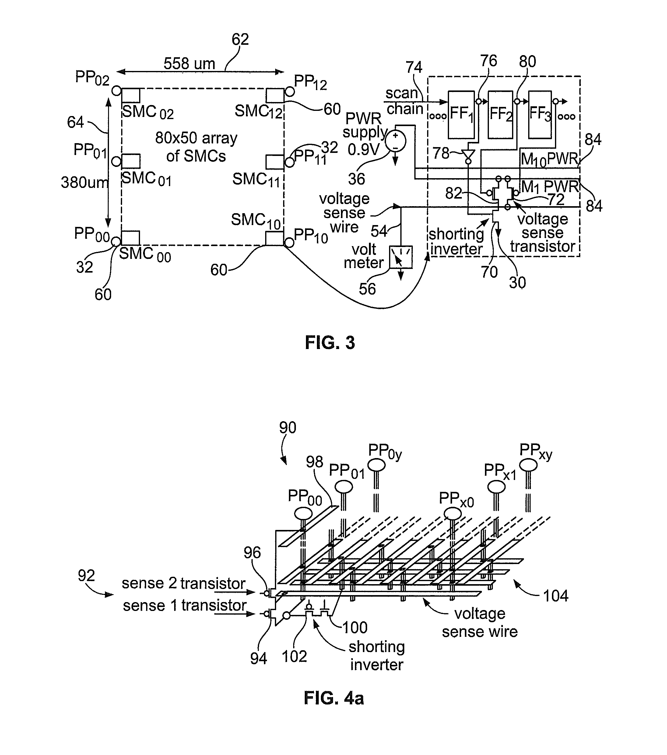
[0041]FIG. 4(b) further illustrates the embodiment 90 having the modified SMC 92, and has like components of FIG. 3(b) identified with similar references numbers. The SMC 90 includes a shorting inverter having a lower transistor 100 that has a drain connected to the ground grid 30, a first voltage sense transistor 94 that has a drain connected to the voltage sense wire 54, and a set of three scan flip-flops FF1, FF2, and FF3. The volt meter 56 is connected to the voltage sense wire 54 and measures the voltage at this node of the SMC circuit 90. The flip-flop FF1 receives a scan chain input 74. The flip-flop FF1 further provides an output 76 to the flip-flop FF2 and an inverter 78. Output from the inverter 78 is provided to the gate of the lower transistor 100 of the shorting inverter. Output from the flip-flop FF1 is also provided via line 106 to the gate of the upper transistor 102 of the shorting inverter. The flip-flop FF2 has an output 80 provided to flip-flop FF3 and also a gat...
embodiment 110
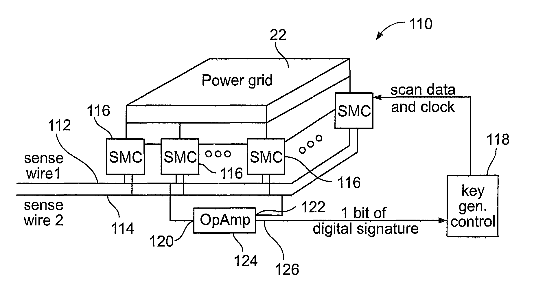
[0044]In another embodiment 110 of the present invention shown in FIG. 5, an increase in the number of stimulus / response pairs is provided, which allows the stimulus to be applied from more than one SMC. In this embodiment 110, multiple shorting inverters are enabled simultaneously at different locations and the voltage drops are measured using different combinations of transistor pairs each connected to one of a first voltage sense wire 112 or a second voltage sense wire 114. The present application refers to these scenarios as “multiple-on” scenarios and the former embodiments 60 and 90 as “single-on” scenarios. Since the power grid is a linear system, superposition applies. Therefore, to make the IC more resilient to attack, where an attacker systematically deduces the voltage drops that would occur under a multiple-on scenario by measuring the voltage drops under all single-on scenarios, the present embodiment can include an obfuscation of the scan chain control bits. Under obfu...
embodiment 130
[0058]Another embodiment 130 of the present invention may provide an increase in the number of single-on scenarios, as shown in FIG. 10. The embodiment 130 can include additional voltage sense transistors 132 that connect to each of the metal layers, e.g., M1 through M10, in a vertical fashion. This allows 10 voltage drops and equivalent resistances based on the number of metal layers to be measured from each SMC. Flip-flops FF2 through FF5 drive the inputs from a respective flip-flop and provide outputs 134-140, respectively, to a 4-to-16 inverting decoder 142 which functions to produce a single low logic ‘0’ on one of the voltage sense transistors when driven with a specific bit pattern. The inverting decoder 142 can be designed such that an input bit pattern of all high logic ‘1’s disables all voltage sense transistors.
PUM
| Property | Measurement | Unit |
|---|---|---|
| electrical current | aaaaa | aaaaa |
| width | aaaaa | aaaaa |
| width | aaaaa | aaaaa |
Abstract
Description
Claims
Application Information
 - R&D
- Intellectual Property
- Life Sciences
- Materials
- Tech Scout
- Unparalleled Data Quality
- Higher Quality Content
- 60% Fewer Hallucinations
Browse by: Latest US Patents, China's latest patents, Technical Efficacy Thesaurus, Application Domain, Technology Topic, Popular Technical Reports.
© 2025 PatSnap. All rights reserved.Legal|Privacy policy|Modern Slavery Act Transparency Statement|Sitemap|About US| Contact US: help@patsnap.com


