Imaging apparatus, imaging system, control method of imaging apparatus, and program

a control method and imaging technology, applied in the field of imaging apparatus, can solve the problems of not being able to record imaging images with a sense of resolution, a selection area with an extremely low mtf, etc., and achieve the effect of superior

Inactive Publication Date: 2013-12-17
SONY CORP
View PDF4 Cites 8 Cited by
  • Summary
  • Abstract
  • Description
  • Claims
  • Application Information

AI Technical Summary

Benefits of technology

[0009]In the techniques in the related art described above, in a case where the focus evaluation value of a plurality of ranging areas is compared, it is possible to remove the effect of MTF characteristics by correcting the BPF characteristics. According to this, in the techniques in the related art described above, it becomes easier to select a ranging area with a low MTF. As a result, it is possible to select a comparatively more appropriate ranging area in a case where the rate of decrease of MTF is comparatively small.
[0012]An imaging apparatus, a control method of the same and a program which executes the method on a computer according to a first embodiment of the invention are provided with an imaging section which converts incident light which is incident from a subject via a lens and generates an imaging image; a selection section which, in regard to each of a plurality of ranging areas arranged in the generated imaging image, obtains a subject distance which is the distance from the lens to a subject included in the ranging area and an MTF for each of the ranging areas in relation to the lens, and selects a ranging area which includes a subject to be a focusing target as a focusing target area based on the obtained subject distance and MTF; and a focus control section which performs focus control so as to focus on a subject included in the selected focusing target area. According to this, an effect is provided where, in regard to each of the plurality of ranging areas, the subject distance and the MTF are obtained, the focusing target area is selected based on the obtained subject distance and MTF, and the focus control is performed so as to focus on the subject included in the selected focusing target area.
[0014]In addition, it is desirable that, in a case where it is determined whether or not the ranging area which includes the subject where the subject distance is the shortest and the ranging area where the MTF is the highest are the same and the ranging areas are not the same, in a case where the MTF of the ranging area which includes the subject where the subject distance is the shortest is small on the basis of a threshold value, the selection section removes the ranging area from the selection target of the focusing target area and performs the determination with regard to each of the ranging areas which are selection targets of the focusing target area after the removal. According to this, an effect is provided where, in the case where it is determined whether or not the ranging area which includes the subject where the subject distance is the shortest and the ranging area where the MTF is the highest are the same and the ranging areas are not the same, in a case where the MTF of the ranging area which includes the subject where the subject distance is the shortest is small on the basis of a threshold value, the ranging area is removed from the selection target of the focusing target area and the determination is performed with regard to each of the ranging areas which are selection targets of the focusing target area after the removal.
[0015]In addition, it is desirable that, in the case where the ranging area which includes the subject where the subject distance is the shortest and the ranging area where the MTF is the highest are not the same, in a case where a rate of decrease of the MTF of the ranging area which includes the subject where the subject distance is the shortest with regard to the ranging area where the MTF is the highest is small on the basis of a threshold value, the selection section selects the ranging area which includes the subject where the subject distance is the shortest as the focusing target area. According to this, an effect is provided where, in the case where the ranging area which includes the subject where the subject distance is the shortest and the ranging area where the MTF is the highest are not the same, in a case where the rate of decrease of the MTF of the ranging area which includes the subject where the subject distance is the shortest with regard to the ranging area where the MTF is the highest is small on the basis of a threshold value, the ranging area which includes the subject where the subject distance is the shortest is selected as the focusing target area.
[0020]In addition, it is desirable that a detection section, which detects a specific target object which is included in the generated imaging image, is further provided, and the selection section arranges the ranging areas on the basis of a position of the detected specific target object in the generated imaging image. According to this, an effect is provided where the specific target object which is included in the generated imaging image is detected and the ranging areas are arranged on the basis of a position of the specific target object in the generated imaging image.
[0022]According to the invention, a superior effect is able to be obtained where it is possible for an appropriate ranging area to be set in consideration of MTF characteristics.

Problems solved by technology

However, in the techniques in the related art described above, even in a case where the rate of decrease of MTF is comparatively large, since it is easier for a ranging area with a low MTF to be selected, there is concern that a ranging area with an extremely low MTF will be selected.
In this manner, in the case where a ranging area with an extremely low MTF is selected, there is concern that it may not be possible to record an imaging image with a sense of resolution.

Method used


Image

  • Imaging apparatus, imaging system, control method of imaging apparatus, and program
  • Imaging apparatus, imaging system, control method of imaging apparatus, and program
  • Imaging apparatus, imaging system, control method of imaging apparatus, and program

Examples


first embodiment

1. First Embodiment

[0040]Internal Configuration Example of Imaging System

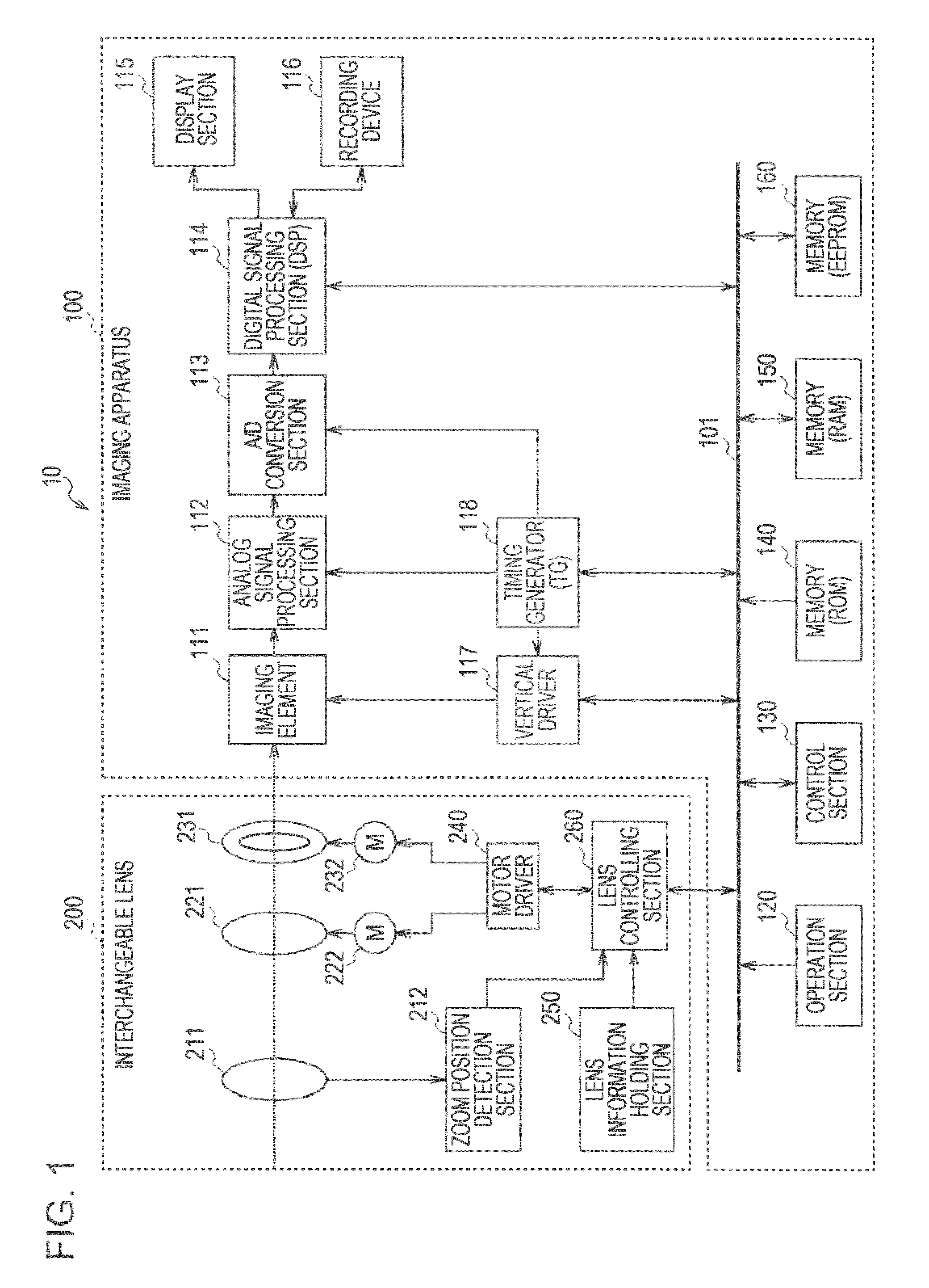
[0041]FIG. 1 is a block diagram illustrating an internal configuration example of an imaging system 10 according to a first embodiment of the invention. The imaging system 10 is provided with an imaging apparatus 100 and an interchangeable lens 200. It is possible to realize the imaging system 10 using, for example, a digital still camera where the lens is able to be interchanged (for example, a digital single-lens camera).

[0042]The imaging apparatus 100 is an imaging apparatus which images a subject, generates image data (imaging images), and records the generated image data as image content (still image content or moving image content). In addition, it is possible for the interchangeable lens 200 to be attached to the imaging image 100 via a lens mount (not shown).

[0043]The interchangeable lens 200 is an interchangeable lens unit which is attached to the imaging apparatus 100 via the lens mount (not shown). T...

second embodiment

2. Second Embodiment

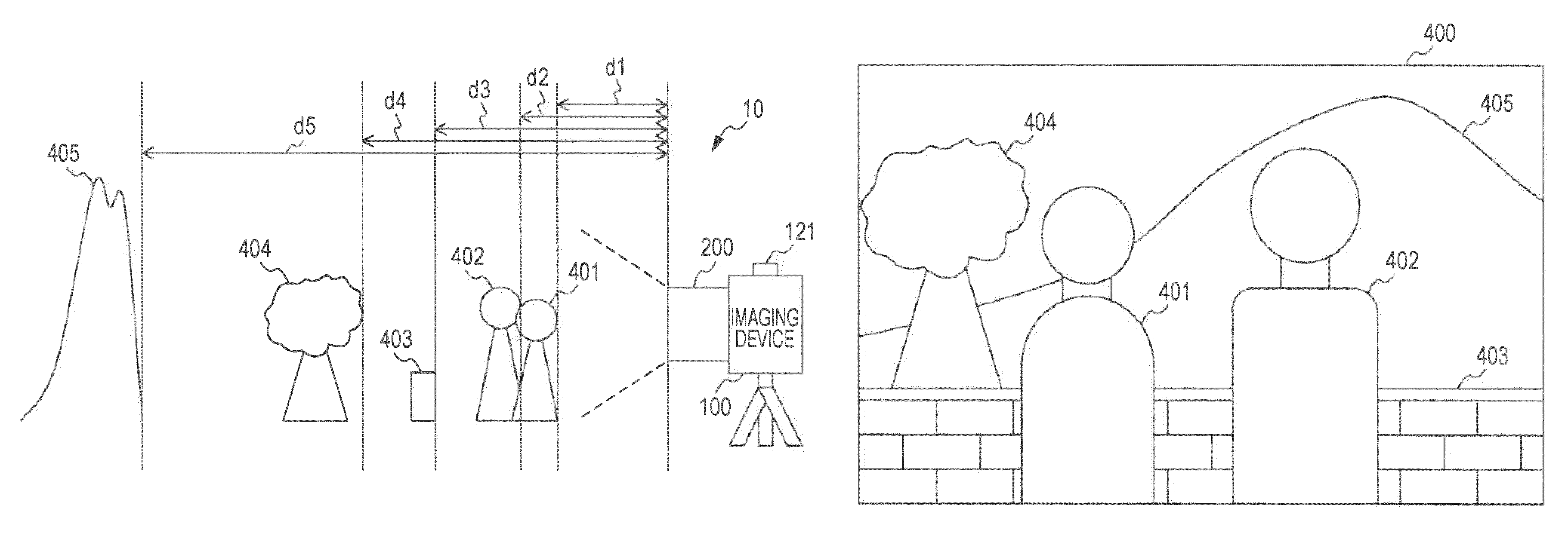
[0155]In the first embodiment of the invention, an example is shown where the focusing target area (final selection area) is selected from the plurality of ranging areas arranged based on a constant regularity (for example, arranged in a 3×5 matrix formation) based on the subject distance and the MTF. Here, for example, in a case where a face is included in the imaging image, it is possible to set the ranging area with regard to the face. In addition, in a case where the imaging image includes a plurality of faces, each of the faces is detected and it is possible to set the ranging areas with regard to each of the detected faces. Therefore, in a case one of the ranging areas is selected from the ranging areas where there are the respective faces, it is possible to apply the first embodiment of the invention. Therefore, in a second embodiment, an example will be described where one of the ranging areas is selected from the ranging areas which are set with regard t...

third embodiment

3. Third Embodiment

[0165]In the first embodiment of the invention, an example is shown where the ranging area is selected in the imaging system 10 where an attachable and detachable type of the interchangeable lens 200 is mounted on the imaging apparatus 100. However, it is possible to apply the first embodiment of the invention to an imaging apparatus such as a digital still camera with a built-in lens. Therefore, in a third embodiment of the invention, an example will be described where the ranging area is selected in the imaging apparatus with a built-in lens. In addition, the configuration of the imaging apparatus according to the third embodiment of the invention is substantially the same as the example shown in FIGS. 1 to 3. As a result, in regard to members which are common with the first embodiment of the invention, the same reference numerals are attached and a portion of the description thereof (external configuration, functional configuration, and the like) is omitted.

[01...


PUM


Abstract

An imaging apparatus is provided which includes an imaging section which converts incident light which is incident from a subject via a lens and generates an imaging image; a selection section which, in regard to each of a plurality of ranging areas arranged in the generated imaging image, obtains a subject distance which is a distance from the lens to a subject included in the ranging area and an MTF for each of the ranging areas in relation to the lens, and selects a ranging area which includes a subject to be a focusing target as a focusing target area based on the obtained subject distance and MTF; and a focus control section which performs focus control so as to focus on a subject included in the selected focusing target area.

Description

BACKGROUND OF THE INVENTION[0001]1. Field of the Invention[0002]The present invention relates to an imaging apparatus, and in particular, to an imaging apparatus and an imaging system provided with an autofocus function, a control method of the same, and a program which executes the method on a computer.[0003]2. Description of the Related Art[0004]In recent years, imaging apparatuses, such as digital still cameras or digital video cameras (for example, a recorder integrated with a camera) which image a subject such as a person or an animal, generate image data (imaging images), and record the image data as image content, have become widespread. In addition, imaging apparatuses provided with an autofocus function where the focus is automatically adjusted are widespread.[0005]As an imaging apparatus provided with an autofocus function, for example, there is an imaging apparatus which arranges a plurality of ranging areas in the generated imaging image and selects an optimal ranging ar...

Claims


Application Information

Patent Timeline
Patent Type & Authority Patents(United States)
IPC IPC(8): H04N5/228H04N5/232
CPCG02B7/365H04N5/23212G03B13/36G03B3/10H04N23/675H04N23/673H04N25/615
Inventor TERASHIMA, YOSHITO
Owner SONY CORP
Why Eureka
Try Eureka