Self-drilling screw

a self-drilling screw and screw body technology, applied in the direction of threaded fasteners, screws, fastening means, etc., can solve the problems of reduced failure rate, small heat generation, and small wear of self-drilling screws, so as to improve the cutting depth, the effect of reducing the failure ra

Active Publication Date: 2013-12-24
HILTI AG
View PDF19 Cites 3 Cited by
  • Summary
  • Abstract
  • Description
  • Claims
  • Application Information

AI Technical Summary

Benefits of technology

[0009]With a self-drilling screw according to the invention, application of a high pressure to each of the at least one first cutting edge and the at least one second cutting edge becomes possible at the beginning of a drilling process after penetration of the drilling tip into a to-be-drilled component. Simultaneously, a symmetrical distribution of the cutting force, which is independent from the pressure force, is achieved. The self-drilling screw according to the present invention permits to produce boreholes with a precisely determined diameter, which leads to a holding force of the set self-drilling screw, which is independent on the pressure force. The drilling feed is noticeably improved.
[0010]In a technically easily realisable embodiment of the invention, the first cutting edge extends, proceeding from an axial region of the drilling tip adjacent to the longitudinal axis, to a first radius, and the second cutting edge extends from an outer radius of the drilling tip toward the longitudinal axis up to a second radius. Thereby, due to a greater cutting depth, thicker chips are produced and a smaller surface on the chips is generated. As a result, a smaller cutting power is required, a smaller amount of heat is produced, and the self-drilling screw is subjected to a smaller wear, all of which leads to a reduced failure rate.
[0012]It is advantageous when the first and second cutting edges have a height above their respective cutting edge bases of from 0.05 mm to 0.5 mm. Thereby, the cutting edges can penetrate sufficiently deep into the drilled material.
[0013]It is further advantageous when the self-drilling screw has a third cutting edge provided at a free end of the drilling tip, extending transverse to the longitudinal axis and adjoining the first cutting edge radially outwardly. With a third cutting edge formed as a cross-cutting edge, a stable tip is formed that can operate, without being broken, at a start of a drilling process even at a high contact pressure.

Problems solved by technology

As a result, a smaller cutting power is required, a smaller amount of heat is produced, and the self-drilling screw is subjected to a smaller wear, all of which leads to a reduced failure rate.

Method used


Image

  • Self-drilling screw
  • Self-drilling screw
  • Self-drilling screw

Examples


Embodiment Construction

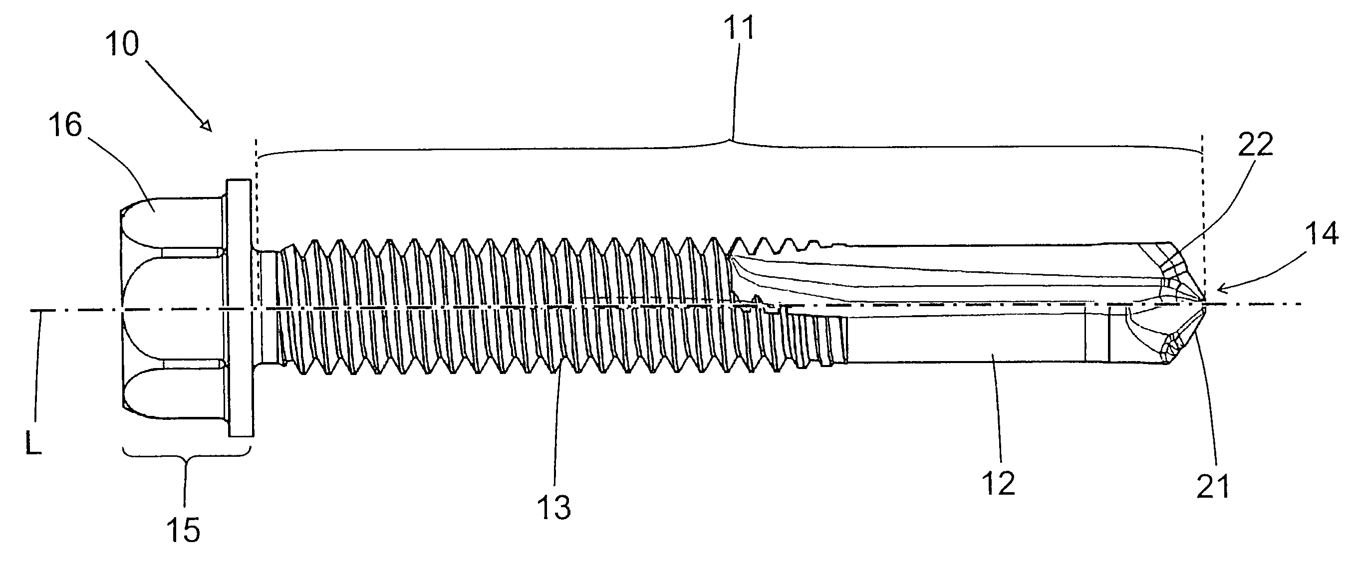
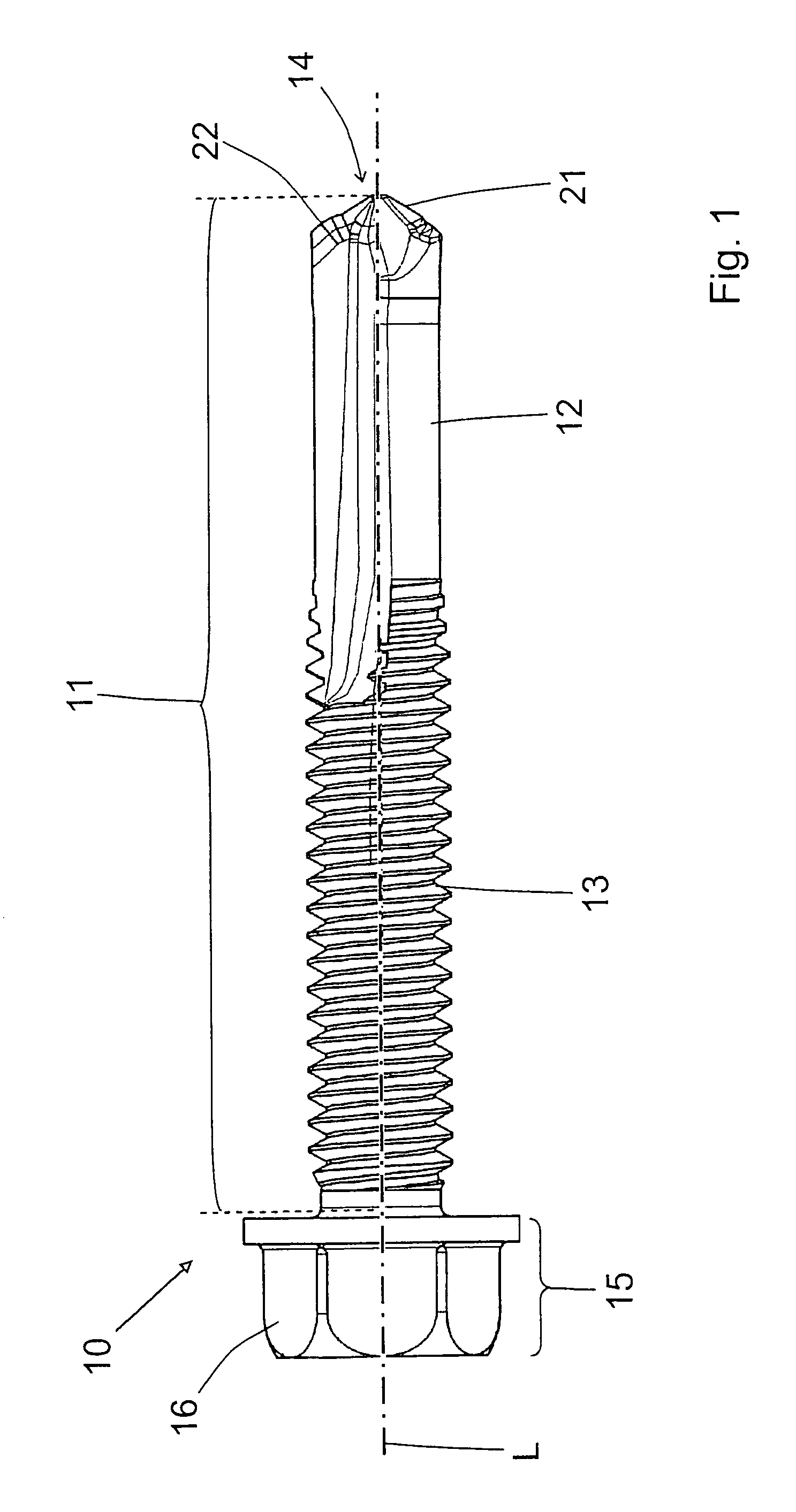
[0020]A self-drilling screw 10 according to the present invention, which is shown in FIGS. 1 through 3, has a shaft 11 carrying a thread 13, a drilling tip 12 provided at one end of the shaft 11, and a head 15 provided at an opposite end of the shaft 11. A longitudinal axis L of the self-drilling screw 10 defines an axial direction of the self-drilling screw 10. The head 15 is provided with rotation transmitting means 16 for a screwdriving tool. As a screwdriving tool, a screwdriving bit or wrench can be used.

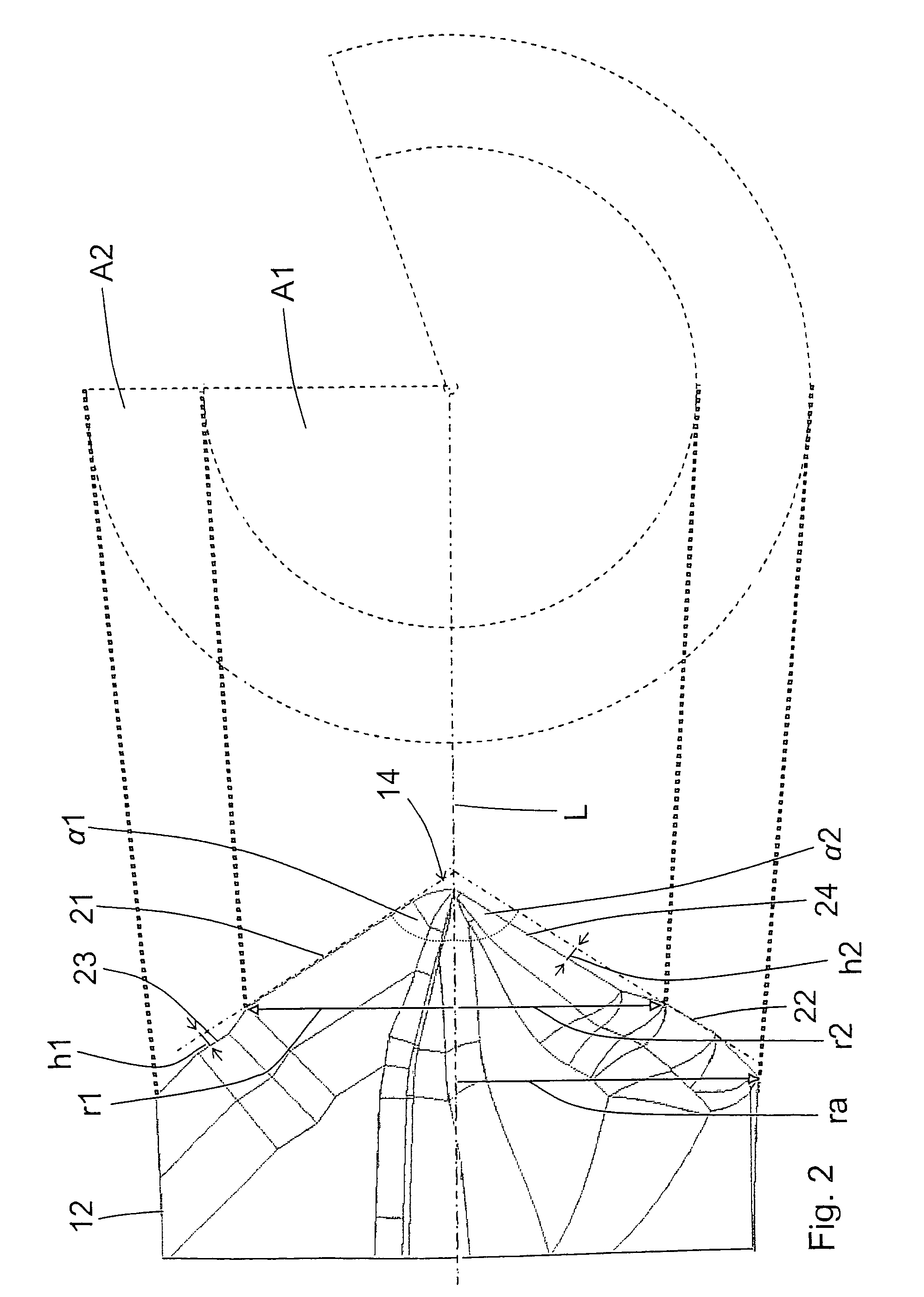
[0021]The drilling tip 12 has at its free end 14 at least one first cutting edge 21 and at least one second cutting edge 22. The first cutting edge 21 is provided exclusively in a radially inward, with respect to the longitudinal axis L, region of the drilling tip 12, and the second cutting edge 22 is provided exclusively in the radially outer region of the drilling tip 12.

[0022]FIG. 2 shows two offset enveloping conical circumferential surfaces A1 and A2. The first cutting edg...


PUM


Abstract

A self-drilling screw (10) has a first cutting edge (21) provided exclusively in a radially inner region of the drilling tip (12), extending at a first acute angle (α1) to the longitudinal axis (L), and a second cutting edge (22) provided in radially outer region of the drilling tip (12) and extending at a second acute angle (α2) to the longitudinal axis (L), with a first enveloping conical circumferential surface (A1) which is defined by the first cutting edge (21) corresponding, with a maximum deviation of + / −10%, to a second enveloping conical circumferential surface (A2) defined by the second cutting edge (22), and with the first acute angle (α1) corresponding, with a maximum deviation of + / −5°, to the second acute angle (α2).

Description

BACKGROUND OF THE INVENTION[0001]1. Field of the Invention[0002]The present invention relates to a self-drilling screw having a shaft provided with a thread at least in some of its regions and defining a longitudinal axis, a drilling tip provided at one end of the shaft, a head provided at another, opposite end of the shaft, and at least one first cutting edge and at least one second cutting edge both provided in the drilling tip.[0003]2. Description of the Prior Art[0004]U.S. Patent Publication US 2004 / 0018069 discloses a self-drilling screw having a shaft, a head provided at one end of the shaft, and a drilling tip provided at the end of the shaft remote from the head. The drilling tip has a first cutting edge located in the radially outer region of the drilling tip, and a second cutting edge extending from a radially inner region to the radially outer region. The first cutting edge extends to the longitudinal axis of the self-drilling screw at a first acute angle, and the second ...

Claims


Application Information

Patent Timeline
Patent Type & Authority Patents(United States)
IPC IPC(8): F16B25/10
CPCF16B25/0031F16B25/0084F16B25/103
Inventor LOICHINGER, ALBERTBAUMGARTNER, MICHAELMATTHIESEN, SVEN
Owner HILTI AG
Why Eureka
Try Eureka