Method for tensioning screw bolts, as well as screw bolt and screw bolt tensioning device for carrying out the method

a technology of screw bolts and tensioning devices, which is applied in the direction of screws, load-modified fasteners, fastening means, etc., can solve the problems of affecting the reduction of space requirements

Active Publication Date: 2013-12-31
HOHMANN FRANK +1
View PDF25 Cites 7 Cited by
  • Summary
  • Abstract
  • Description
  • Claims
  • Application Information

AI Technical Summary

Benefits of technology

[0008]By means of the measures of the invention, the length of the bolt end protruding from the nut, which is required for transmitting the pretensioning force, can be reduced considerably, so that both the required total length of the screw bolt and the corresponding dimensions of the screw bolt tensioning device are distinctly reduced. Since the bolt end in accordance with the invention is provided with an external thread and with an internal thread and the required total pretensioning force is applied only for one part via the external thread and for the remaining part via the internal thread, the external thread is relieved, so that its required length can be reduced without the same shearing off. The division of the total pretensioning force on the external thread and the internal thread can vary and is adapted to the respective requirements.
[0011]With a screw bolt tensioning device, a screw bolt whose bolt end has an external thread and an internal thread can be tensioned in a simple and space-saving manner. Since an outer exchange bushing is formed for the external thread of the bolt end and an inner exchange bushing is formed for the internal thread of the bolt end, wherein the inner exchange bushing is rotatable and axially displaceable with respect to the outer one, both can independently be screwed to the bolt end. In this way, the respective pairs of thread and counterthread also are independent of each other and can optimally be adapted to the respective requirements separate from each other. Thus, the threads for example can also be designed conically. Each exchange bushing is axially displaceable by means of its own piston, wherein both pistons are connected to a pressure-medium source such that a simultaneous application of the respective pretensioning force portions (components) to the respective threads is ensured. For example, the pressure-medium source or the pressure-medium port can be designed as a uniform or common pressure-medium port. In this application, the term “pressure medium” relates to hydraulic pressure media. The active piston areas of the first and the second piston have the same size ratio relative to each other as the components of the total pretensioning force to be transmitted by the two exchange bushings.
[0013]The same preferably is indicated in that in the relaxed condition of the spring the second end of the inner exchange bushing protrudes from a lid of the screw bolt tensioning device, which is mounted on the second end face of the cylinder opposite the supporting surface, by a specified length, wherein the spring deflection is so great that the inner exchange bushing can be displaced by a specified amount before being screwed into the bolt end. When the inner exchange bushing is screwed into the internal thread of the bolt end, this protrusion is reduced, so that the magnitude of the reduction is a measure for the screw-in depth of the inner exchange bushing. In this way, a wrong assembly due to an inner exchange bushing only partly screwed in can be detected and hence can be avoided.
[0015]A screw bolt tensioning device in accordance with the invention advantageously includes a hydraulic valve which can be transferred from a first valve position, in which it blocks the supply of the pressure-medium supplies with pressure medium, into a second valve position, in which it enables said supply, and back by means of an actuator which can be actuated by the inner exchange bushing in specified positions of the same. In this way, it can be achieved that pressure medium only is supplied, i.e. the pretensioning force only is applied, when the inner exchange bushing is correctly screwed to the bolt end. A damage of the screw bolt and / or of the screw bolt tensioning device or even a damage to persons thereby can be prevented.

Problems solved by technology

However, the same require high pretensioning forces for whose introduction into the screw bolt the dimensions of the force-transmitting parts must be increased, which in turn impairs the reduction of the space requirement.

Method used


Image

  • Method for tensioning screw bolts, as well as screw bolt and screw bolt tensioning device for carrying out the method
  • Method for tensioning screw bolts, as well as screw bolt and screw bolt tensioning device for carrying out the method
  • Method for tensioning screw bolts, as well as screw bolt and screw bolt tensioning device for carrying out the method

Examples


Embodiment Construction

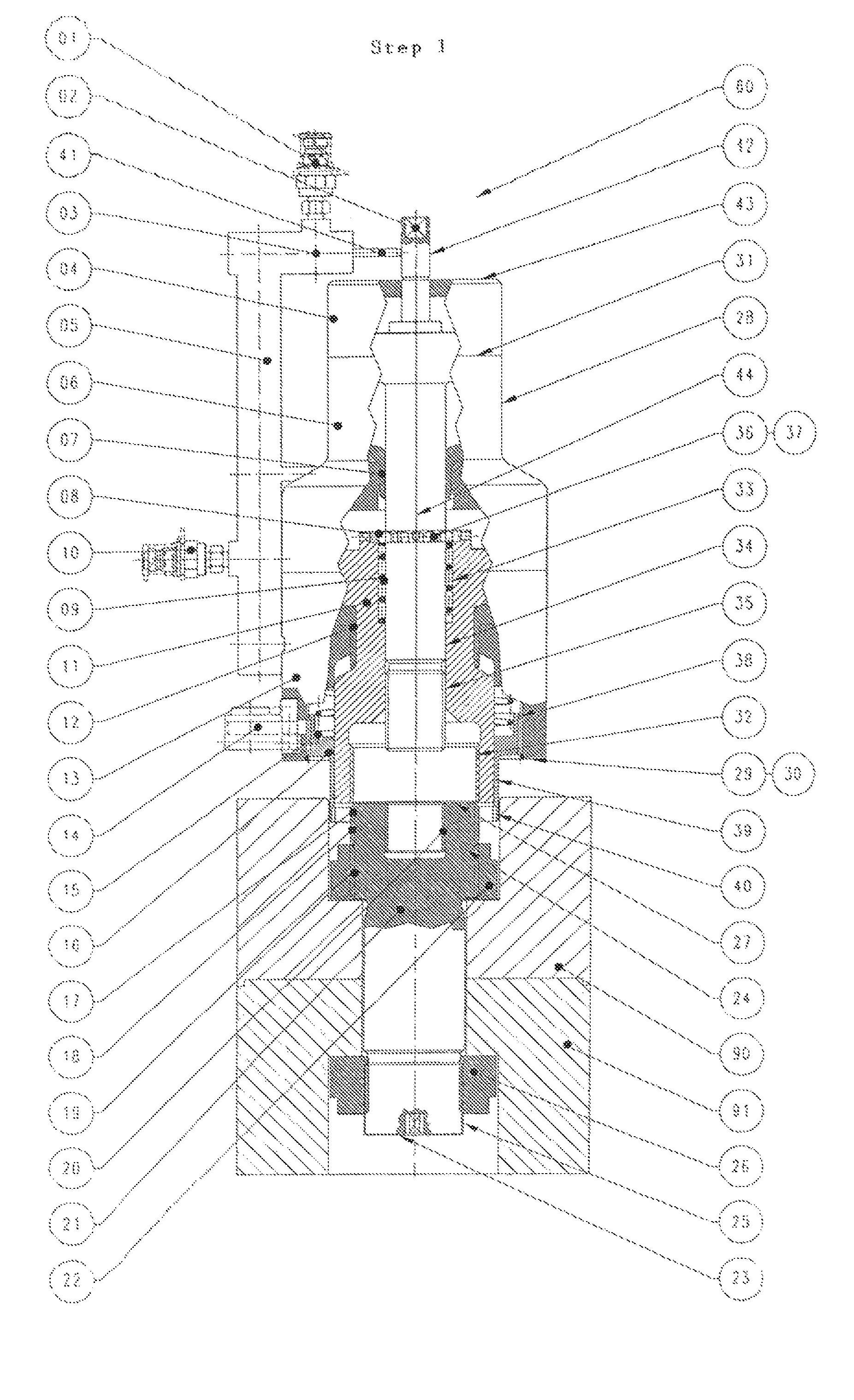
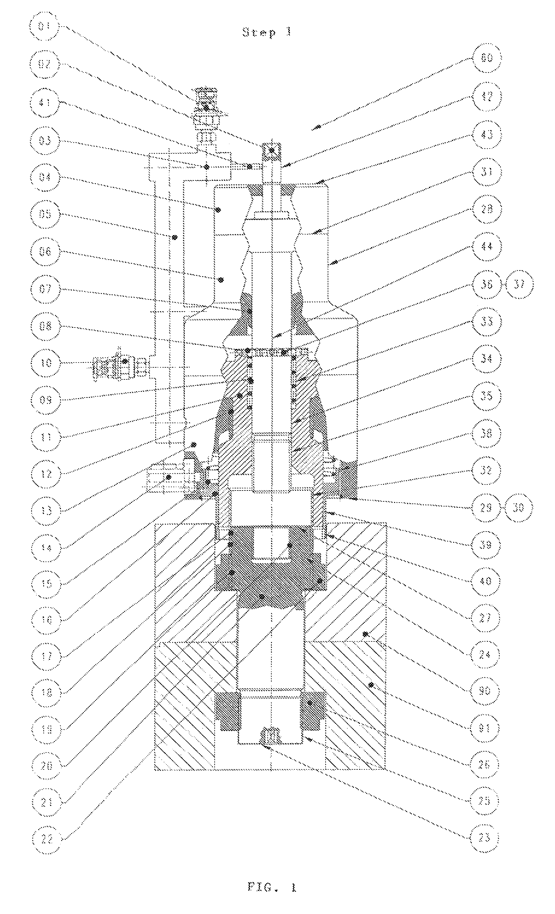
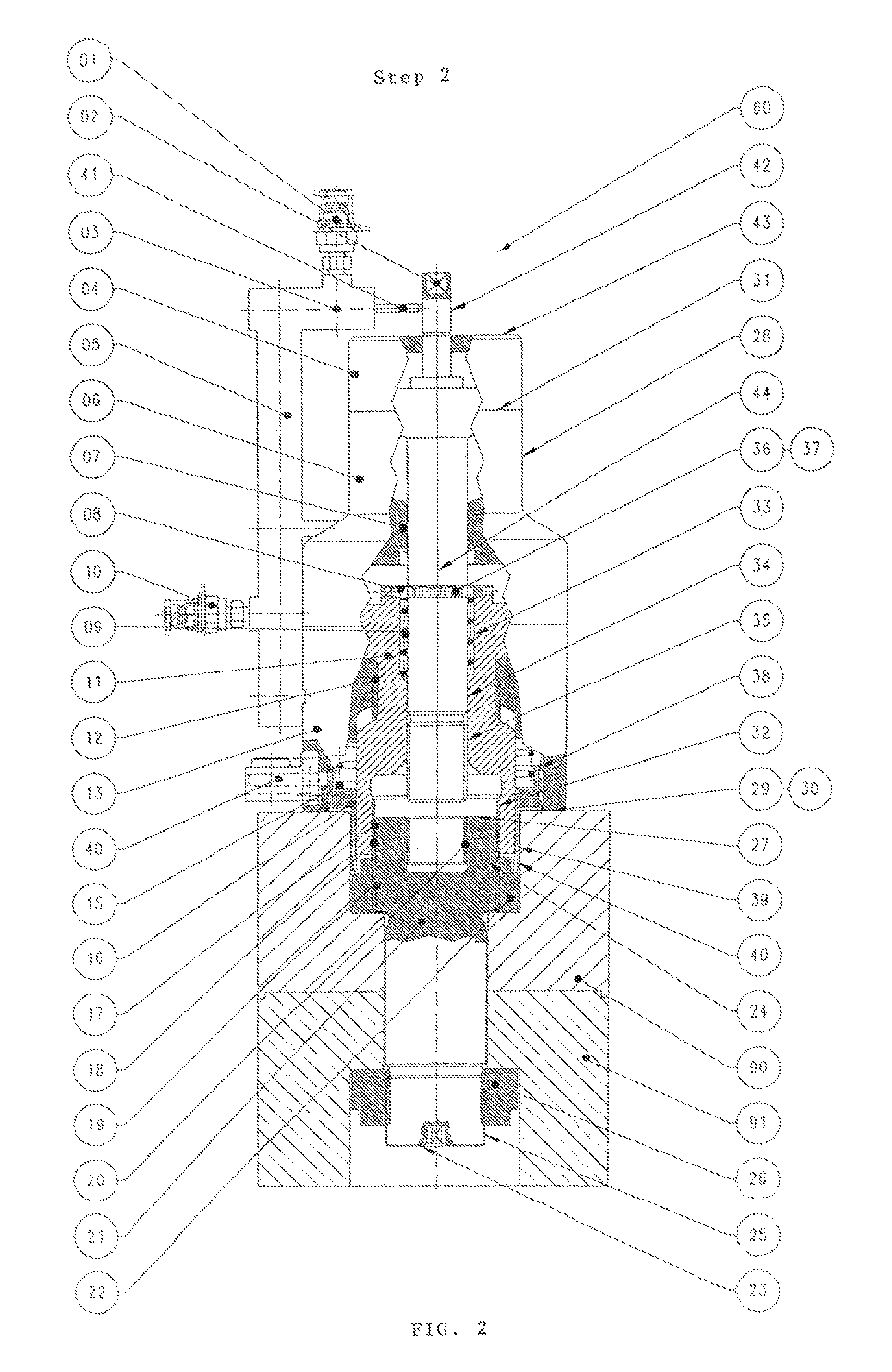
[0020]In the embodiment shown in FIGS. 1 to 5, a screw bolt 21 should clamp two machine parts 90, 91 to each other and therefore be tensioned with a screw bolt tensioning device 60.

[0021]The screw bolt 21 and the screw bolt tensioning device 60 first are described with reference to FIG. 1.

[0022]The screw bolt 21 is sunk into the machine parts 90, 91, which are clamped to each other both with the bolt head 23 and with the bolt end 24. The bolt head 23 includes an external thread 25 onto which a nut 26 is screwed. The nut 26 rests against the lower machine part 91 as shown in the Figures.

[0023]The bolt end 24 includes an external thread 18 and an internal thread 20 extending coaxially thereto from the end face 27, i.e. from the end surface. With respect to the formation and direction of rotation, these threads 18, 20 are independent of each other in the illustrated embodiment and can optimally be adapted to the respective requirements. For example, the threads can also have a conical ...


PUM

PropertyMeasurementUnit
outer diameteraaaaaaaaaa
diameteraaaaaaaaaa
timeaaaaaaaaaa

Abstract

This invention relates to a method for hydraulically tensioning screw bolts as well as to screw bolts and screw bolt tensioning devices for carrying out the method. It is proposed to apply the total pretensioning force for one part via an external thread and for the remaining part via an internal thread of the bolt end.

Description

CROSS-REFERENCE TO RELATED APPLICATION(S)[0001]This Non-Provisional United States patent application relies for priority on U.S. Provisional Patent Application Ser. No. 61 / 300,659, filed on Feb. 2, 2010, and on German Utility Model Application No. 10 2010 006 562.5, filed on Feb. 2, 2010, the contents of both of which are incorporated herein by reference.FIELD OF THE INVENTION[0002]This invention relates to a method for tensioning screw bolts which extend through machine parts to be clamped to each other and include a bolt head, which is supported on one side of the machine parts, and include a bolt end which is provided for being screwed to a screw bolt tensioning device. Furthermore, this invention relates to screw bolts and screw bolt tensioning devices for carrying out the method.DESCRIPTION OF THE RELATED ART[0003]In the present application, the term “bolt end” refers to the end of the screw bolt which is engaged by a screw bolt tensioning device. The other end of the screw bol...

Claims


Application Information

Patent Timeline
Patent Type & Authority Patents(United States)
IPC IPC(8): B21D39/00F16B31/00B25B29/02
CPCF16B31/043B25B29/02B23P19/067Y10T29/49874Y10T29/49963
Inventor HOHMANN, FRANKHOHMANN, JORG
Owner HOHMANN FRANK
Why Eureka
Try Eureka